
What is a Pulse Output?
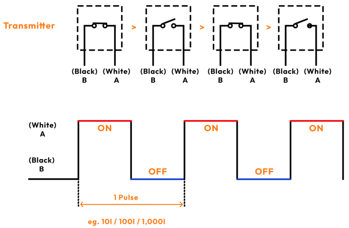
In the gas flow meter and water meter industry, a pulse output is an electronic signal generated by the meter to indicate a specific amount of fluid or gas that has passed through it. Each pulse corresponds to a defined volume of gas, water or fluid, such as one liter / 10, 100 and/or 1000 liters per pulse.
These outputs allow integration with data logging equipment, or BMS monitoring systems, enabling accurate tracking and automation of flow measurement.
Types of Pulse Outputs & Where These Outputs Are Commonly Used
Reed Switch
-
Found in mechanical flow meters and basic applications where simplicity is key.
Solid State
-
Common in more advanced meters with programmable output needs, especially in revenue-based metering or where interference resistance is critical.
Optical
-
Used in applications requiring very high-resolution data or in systems where precision flow tracking is essential.
Open Collector
-
Typical of magnetic flow meters (Mag Meters) and other high-performance industrial devices. Often used in automation systems where versatility and reliability are needed.
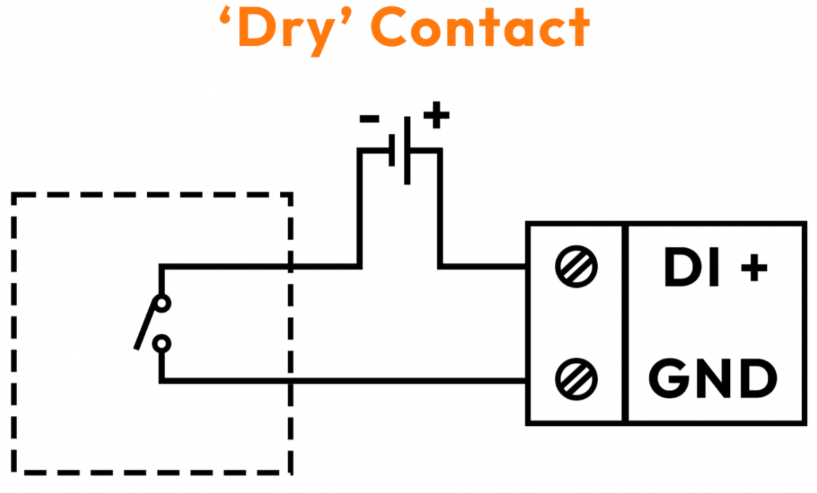
Volt-Free (Dry Contact) Outputs
How it Works:
Volt-free outputs generate pulses by physically opening or closing a circuit. This is typically achieved using components like mechanical switches or solid-state relays. No voltage is supplied directly by the meter; instead, the circuit relies on an external power source connected to the monitoring system. When the circuit is closed, it allows current to flow, signalling a pulse.
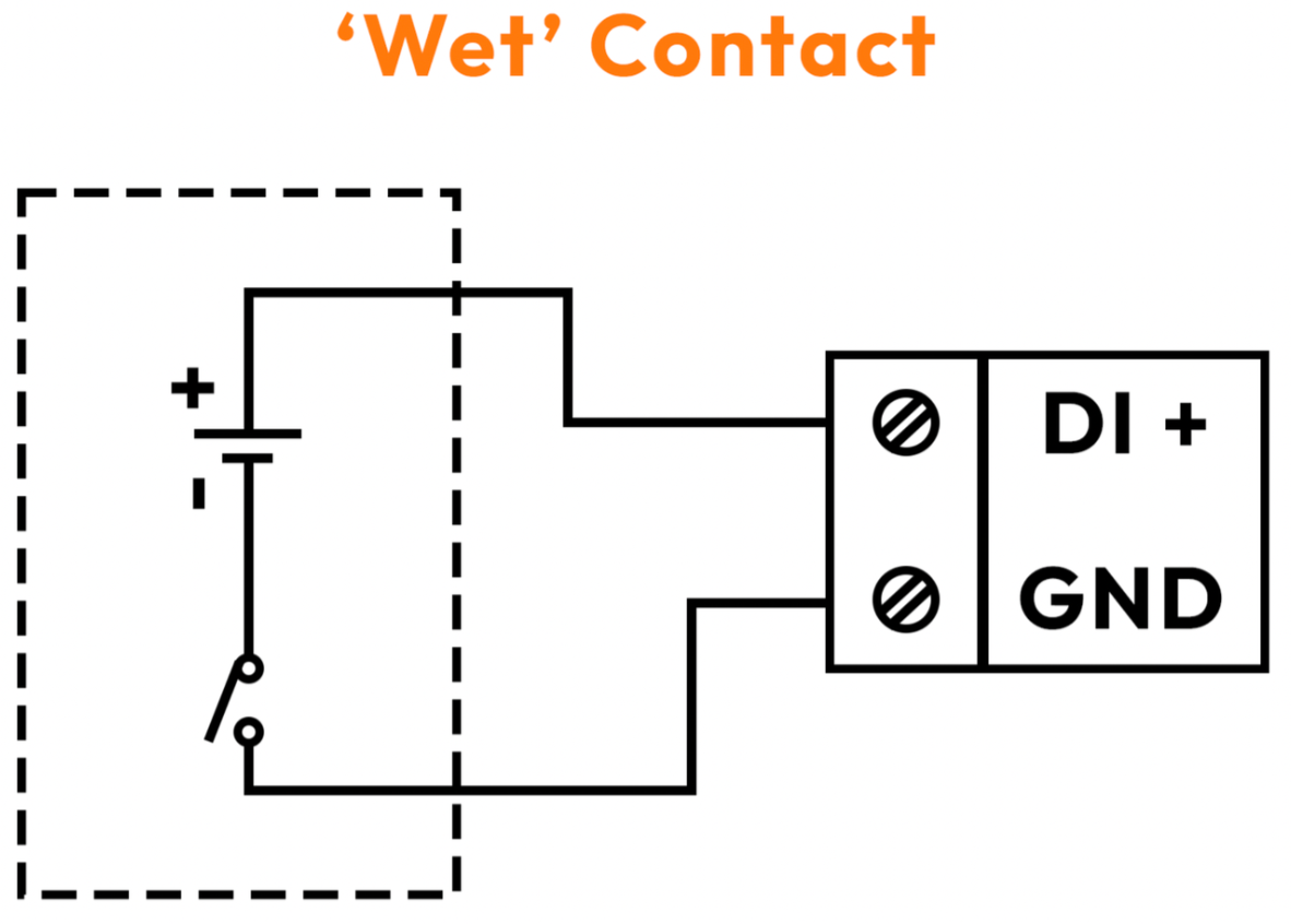
Voltage-Driven Outputs
-
How it Works:
Voltage-driven outputs produce pulses by varying the voltage level in the circuit. For example, a pulse might be represented by a change from 0V (low state) to a predefined higher voltage (e.g., 5V, 12V, or 24V). The voltage change acts as a signal that can be detected by connected monitoring devices.
Pulse Duration, Length & Pulse Transmitting
Pulse Duration: Refers to the time each pulse signal is active (high state). It is typically in the range of milliseconds, such as 50ms, 100ms, 500ms, but it can vary based on the meter and application.
Pulse Length: This measures the distance (or time) between successive pulses and depends on the flow rate and the meter's pulse resolution.
Faster flow rates product shorter pulse lengths, while slower rates lead to longer intervals.
Pro Tips
-
Avoid Overpowering Reed Switches: Ensure the connected device doesn’t exceed the current rating of the reed switch to prevent damage.
-
Check Compatibility: Verify that pulse output and receiving devices have compatible power requirements and configurations (e.g., avoid connecting two powered outputs).
-
Prevent Interference: Use shielded cables and proper grounding to reduce noise and tampering risks.
-
Match Output to Application: Select the appropriate pulse output type based on the required resolution, frequency, and environmental conditions.
Talgil - Pulses Divider
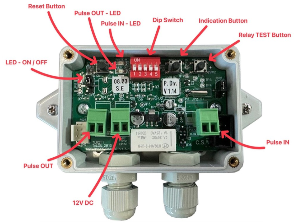
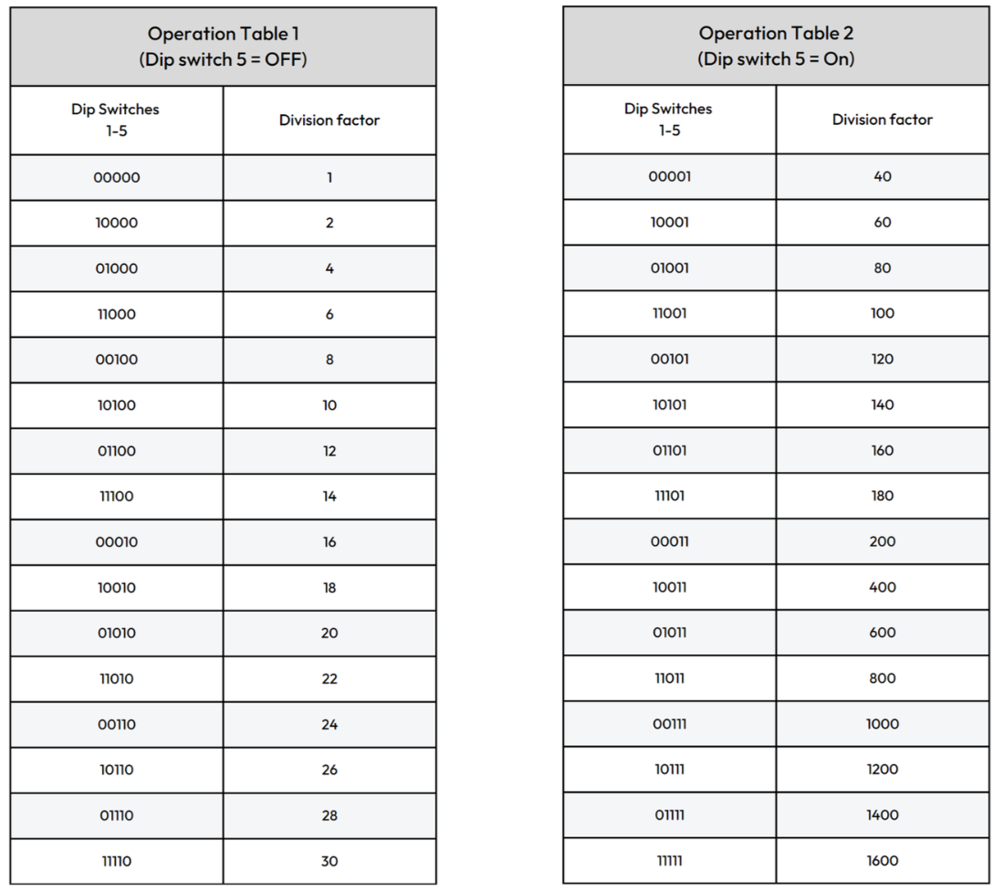
The purpose of the pulse divider unit is to enable BMS controllers to read short or high-rate pulses at a scanning rate of once in a second or lower. The unit expects to receive dry contact inputs, usually from devices such as water meters or gas meters. It will count the pulses and emit a symmetric pulse per each "x" pulse counted, based on the selected setting.
A special case is when x equals 1, then for each pulse received at the input, there will be one pulse generated as output (not necessarily symmetric) whose width will be no less than 1 second. This way, even if the input pulse is narrow, the output pulse will be wide enough not to be missed by the controller. This pulse rate, in this case, cannot be higher than one pulse every 2 seconds.
Note: The minimum pulse is approximately 15 milli-second (33 pulses per second)
Talgil - Pulses Divider - Deeco
The Problem with BMS IO Monitoring High Frequency Meter Pulses
In Building Management System (BMS) applications, digital and universal inputs are often specified with a nominal frequency rating (e.g. 100 Hz), which can misleadingly suggest suitability for high-speed pulse counting applications such as energy metering. In practice, however, these inputs are not designed as true hardware counters and rely on software polling or task-based sampling within the controller.
As a result, when interfacing with high-frequency pulse outputs, such as 1000 imp/kWh energy meters under moderate to high loads, the effective pulse rate can approach or exceed the reliable detection capability of the BMS input. Even though a 100 Hz rating may appear sufficient on paper, real-world performance is constrained by scan time, input filtering, network latency, and controller task scheduling.
This mismatch leads to missed pulses, cumulative measurement errors, and under-reporting of energy consumption, often without any visible fault indication. For this reason, standard digital or universal inputs on BMS I/O modules should not be considered suitable for high-frequency metering applications, and alternative approaches, such as Modbus metering or dedicated high-speed counter inputs or data acquisition modules, should be used instead to ensure accuracy and data integrity.
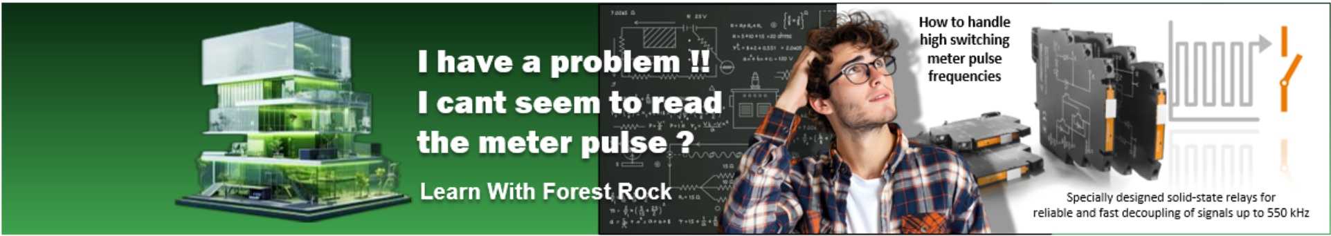
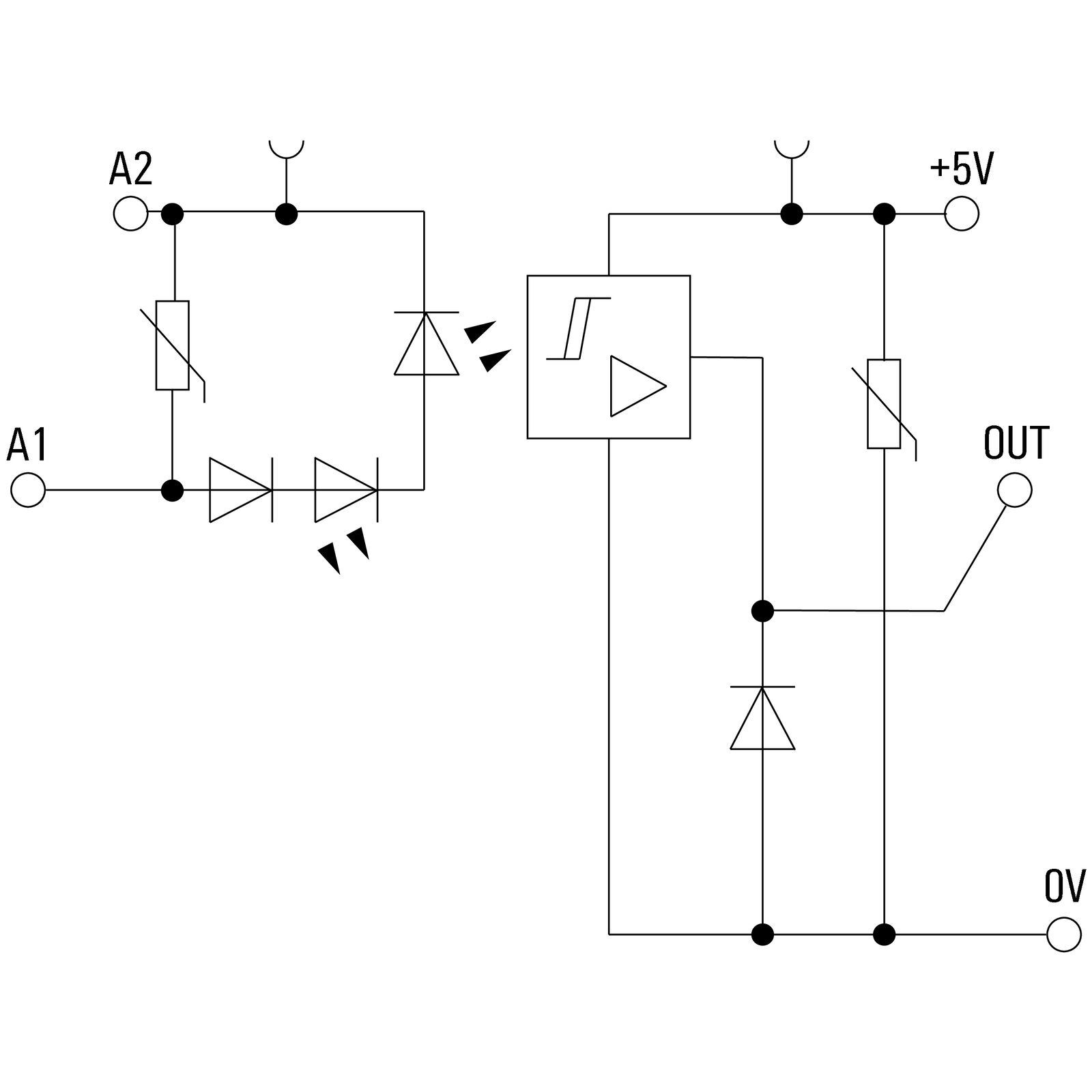
High switching pulse frequencies
What you need are specially designed solid-state relays for reliable and fast decoupling of meter pulse signals up to 550 kHz
Due to their design, solid-state relays can already switch significantly faster than electromechanical relays. However, there are applications in which signals have to be switched even faster or at an even higher frequency. For particularly fast switching processes, or the transmission of signals with high switching frequencies between 1 and 550 kHz, weidmueller have developed special solid-state relays that are precisely tailored to these specific applications.
Other Resources & Customer Survey:
💬 Don't miss out! Follow the Forest Rock News channel on WhatsApp Click Here!
💬 We’d also love your feedback! Please take a moment to complete our quick Customer Survey
It only takes a minute and helps us serve you better!

IoT Devices for BMS, Automation & Smart Connectivity | Forest Rock