

Diagnosing Unstable Modbus Networks
Your Complete Guide to Understanding RS-485 Communications
What is RS-485?
RS-485 (also known as EIA/TIA-485) is a robust communication standard that lets devices talk to each other over long distances. Think of it as a reliable messenger system for industrial equipment, building automation, and control systems.
Key Advantage: RS-485 can send signals up to 4,000 feet (1,200 meters) at speeds reaching 100 kbits/s, making it perfect for large facilities and industrial applications using the correct cable specifications and an example of which is pictured below:

Belden 9842 Has Two Twisted Pairs core colours can vary
22 AWG & Is Shielded Per Pair and also has a drain wire. One of the wires of the second pair will typically be used as "ground"
The fourth wire will be not-used.
RS-485 bus troubleshooting for Modbus RTU communication failures

RS-485 Fault Finding Guide:
Diagnosing Unstable Modbus Networks Or Intermittent Faults?
Overview
You've tested everything.
The Niagara code has been reviewed line by line. The Modbus map is correct. Baud rates match. Every device responds perfectly in the workshop.
Then the system goes live and the problems begin:
-
Random timeouts
-
Invalid CRC errors
-
Devices disappearing and reappearing
-
Corrupted frames
-
Communication failures that cannot be reproduced on demand
If that sounds familiar, the good news is that you're probably not looking for a software problem.
In our experience, most intermittent RS-485 faults originate in the physical layer.
One recent installation consisted of a PLC polling a dozen Modbus RTU slaves over RS-485. The network operated flawlessly during testing, yet failed repeatedly once installed on site. Investigation revealed multiple physical-layer issues:
-
Star topology
-
Incorrect termination locations
-
Unshielded cable on one branch
-
Routing alongside VFD output cables
-
No common signal reference between devices powered from different locations
Once the bus was rebuilt as a proper daisy chain using shielded twisted pair, correctly terminated at the physical ends and provided with a common reference conductor, the communication errors disappeared.
This article explains the diagnostic process our support engineers typically follow when investigating unstable RS-485 networks.
Why RS-485 Fails "Sometimes"
Understanding why RS-485 faults appear intermittent helps narrow down the likely causes.
RS-485 is a differential signalling system. Data is transmitted as the voltage difference between two conductors rather than as a voltage referenced directly to ground.
This provides excellent noise immunity, but it doesn't make the system immune to poor installation practices.
Three characteristics are particularly important.
Differential Does Not Mean Isolated
Many engineers assume that because RS-485 is differential, grounding no longer matters.
Unfortunately, that's not true.
Every RS-485 transceiver has a finite common-mode operating range. If two devices sit at significantly different electrical potentials, communication can become unreliable even when the differential signal itself appears healthy.
This commonly occurs when:
-
Separate panels have different power supplies
-
Devices are installed in different areas of a site
-
Large motors and VFDs introduce shifting ground potentials
The Test Bench Lies
Many RS-485 systems are tested under ideal conditions:
-
Three metres of cable
-
One power supply
-
No motors
-
No VFDs
-
No electrical noise
A production environment introduces:
-
Longer cable runs
-
Multiple power systems
-
High current equipment
-
Significant EMI
What looked like a reliable system in the workshop may have very little noise margin once installed.
The Diagnostic Checklist
Before changing any software, work through the following checks
Step 1 – Draw the Real Network Topology
Do not trust the drawings.
Physically trace the cable route and draw how the network is actually wired.
A compliant RS-485 bus should resemble:
Controller (JACE9000/iSMA MAC36)
|
Device 1
|
Device 2
|
Device 3
|
Device 4
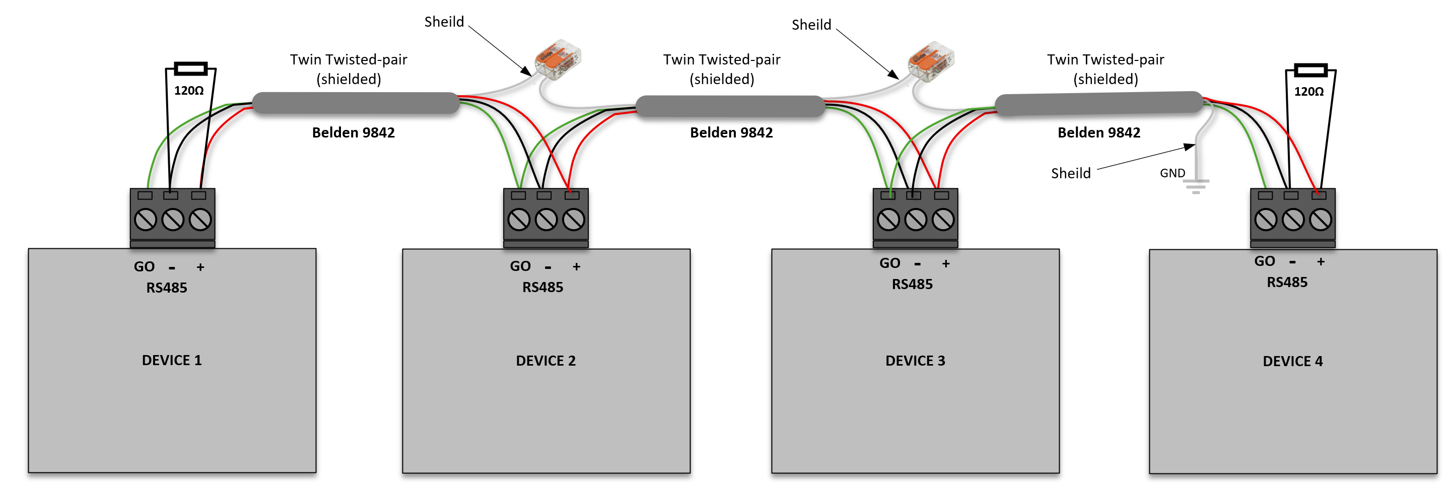
Avoid Star Topologies
We want a daisy chain. Not a star. Not a collection of branches.
Not multiple home runs returning to a central panel.
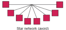
Although this star arrangement may appear to function at first, it often creates intermittent communication failures that become worse as cable lengths increase or baud rates rise.
Watch for Long Stubs
Every branch becomes a reflection point.
As a rule:
-
Keep stubs as short as possible
-
Ideally less than 300 mm
-
Avoid junction boxes that create multiple branches
If multiple long branches are unavoidable, use RS-485 repeaters and treat each branch as a separate bus.
Step 2 – Verify Termination Resistors
RS-485 requires termination at the physical ends of the cable.
Not the lowest device address.
Not the highest device address.
The actual cable ends.
Correct arrangement:
Without proper termination, signals reflect back along the cable and can corrupt data frames.
Correct Configuration
Install a 120 Ω termination resistor at:
-
The first physical device on the bus
-
The last physical device on the bus
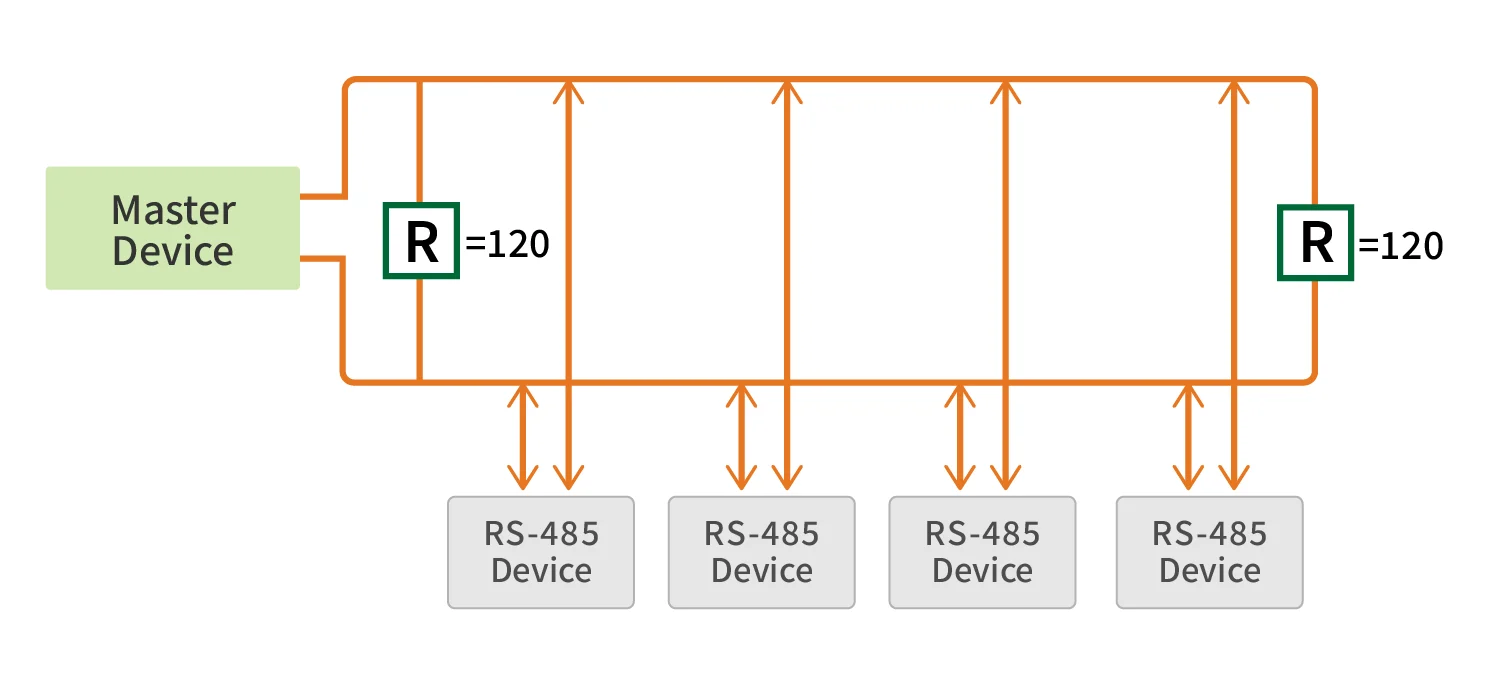
Common Mistakes
No Terminations
Results in signal reflections.
Too Many Terminations
Three or more terminations increase bus loading and reduce signal amplitude.
Terminations in the Wrong Location
The resistor must be at the actual end of the cable, not merely the first and last device addresses.
A device located midway along the cable is not an endpoint regardless of its address.
Step 3 – Confirm Cable Type
Cable selection has a major impact on network reliability.
Recommended Cable
Use:
-
Shielded twisted pair
-
Characteristic impedance near 120 Ω
-
Low capacitance industrial communications cable
Examples include:
-
Belden 9841
-
Belden 3105A
-
Equivalent RS-485-rated cable
Avoid
-
Alarm cable
-
Telephone cable
-
Random spare conductors
-
Untwisted multicore cable
-
Flexible control cable used for convenience
These may work temporarily but often become unreliable as network size increases.
Choosing the Right Cable
Not all cables are created equal! For reliable RS-485 communication, you need a twisted-pair cable with the right specifications.
|
Specification |
Details |
|
Wire Gauge |
22 or 24 AWG solid or stranded conductors |
|
Cable Type |
Twin Twisted-pair (shielded or unshielded) |
|
Shielding |
100% foil shield recommended for noisy environments |
|
Drain Wire |
24 AWG tinned copper drain wire for shield grounding |
|
Insulation |
Polypropylene or similar low-capacitance material |
Recommended Cable: Belden 9841 /9842 are a professional-grade choice, featuring 22 AWG stranded tinned copper conductors, individual shielding for each pair, and a compact design perfect for industrial installations.
Step 4 – Check Shielding and Cable Routing
Many communication problems are actually EMC problems.
Good Practice
Route communications cables:
-
Separately from power cables
-
Separately from VFD outputs
-
Separately from motor cables
-
Away from contactors and switching equipment
Poor Practice
Running RS-485 in the same tray as:
-
Variable frequency drive output cables
-
Large motor feeders
-
Switched power circuits
can introduce sufficient interference to corrupt data packets.
Shield Grounding
In most installations:
-
Connect the cable shield to earth at one end only
-
Maintain continuity through the network
Grounding both ends can create ground loops in some installations.
Always follow the system manufacturer's recommendations where they differ.
Step 5 – Verify the Signal Reference
One of the most overlooked causes of RS-485 faults is the absence of a common reference conductor.
Many engineers focus entirely on A and B.
In reality, devices spread across a large site can develop different ground potentials.
Recommended Practice
Use three conductors: | A | B | COM | OR | G0 | - | + | As Pictured below:
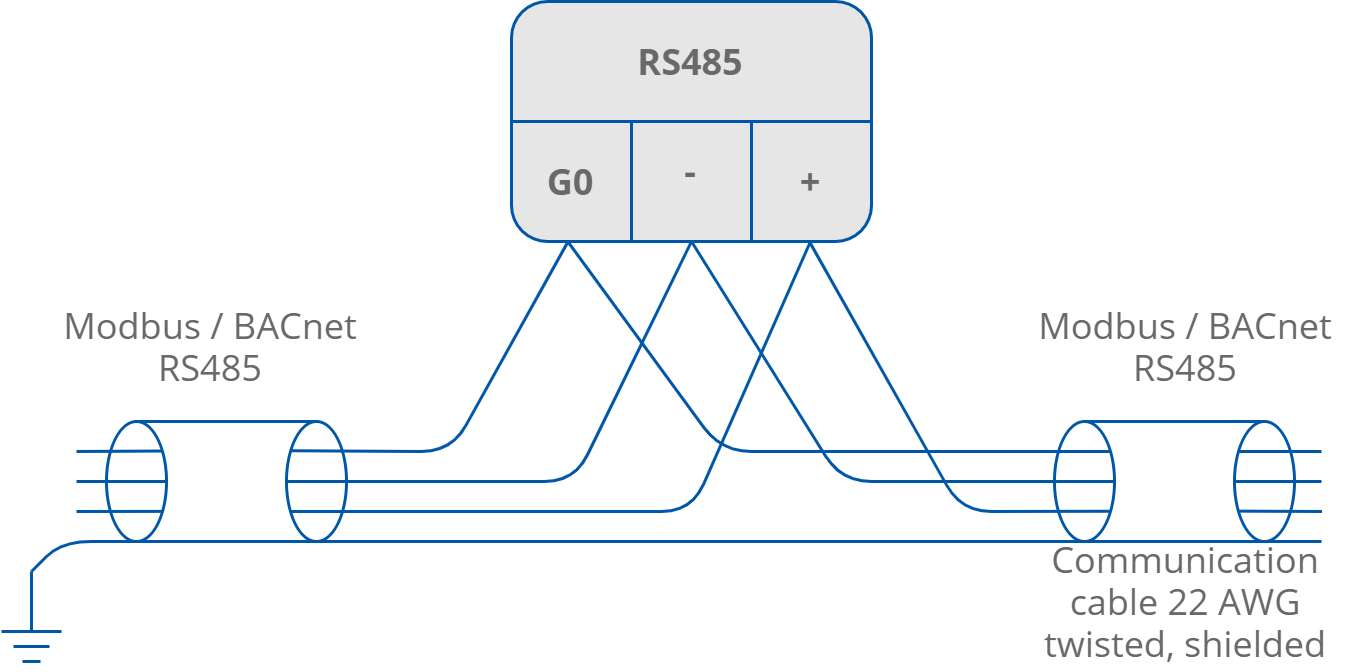
The reference conductor helps maintain a valid common-mode voltage range between devices.
This becomes increasingly important when:
-
Devices are in different panels
-
Devices are supplied from different power sources
-
Cable runs are long
Step 6 – Measure the Bus
Where faults persist, basic mustimeter measurements can quickly identify wiring issues.
Power Off Resistance Check
Disconnect power and measure resistance between:
-
A and B OR - and +
A properly terminated network should typically measure approximately: 60 Ω
The 60 Ω Test
With power removed, measure resistance between A and B.
|
Reading |
Likely Cause |
|---|---|
|
~60 Ω |
Correct |
|
~120 Ω |
One termination missing |
|
~40 Ω or lower |
Additional terminations present |
|
Open circuit |
No termination or cable fault |
This represents two parallel 120 Ω termination resistors.
Readings significantly different from this may indicate:
-
Missing terminators
-
Additional terminators
-
Wiring faults
Many modern BMS devices now have switch-selectable termination resistors.
Common culprits include:
-
BMS Controllers
-
PLCs
-
VFDs
-
Gateways
-
Energy meters
Verify exactly which devices have termination enabled.
Other Electrical Checks That Can Be Made
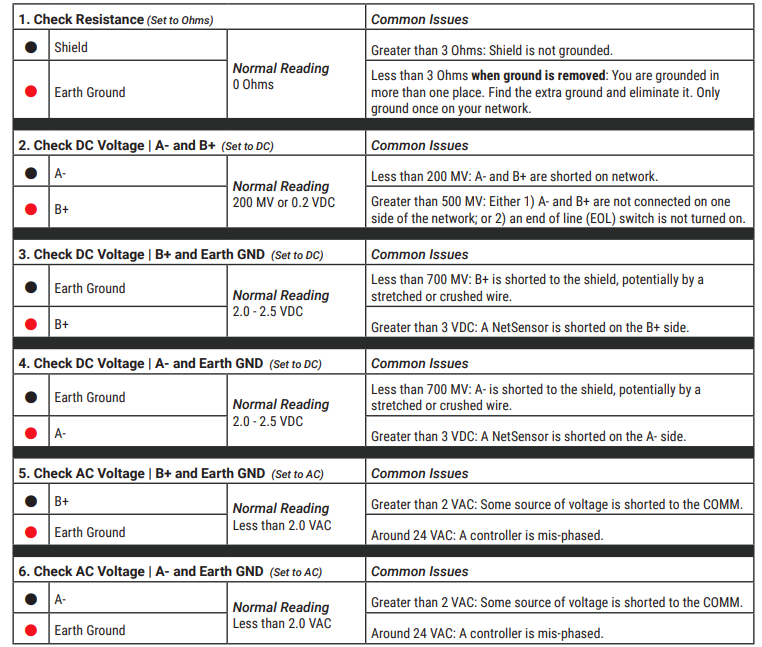
Voltage Checks
With power applied:
-
Measure A to COM
-
Measure B to COM
-
Measure A to B
Look for stable voltages within the device manufacturer's specifications.
Large fluctuations may indicate grounding or interference problems.
Step 7 – Check Fail-Safe Biasing
Termination and biasing are often confused.
Termination controls reflections.
Biasing establishes a known idle state.
Without biasing, the bus can float when no device is transmitting.
This can result in:
-
False start bits
-
Framing errors
-
Corrupted packets
-
Random communications faults
Typically, biasing consists of:
-
Pull-up resistor on one conductor
-
Pull-down resistor on the other
at a single location on the network, usually near the master device.
Quick Check
With the system powered and idle:
-
Measure A-to-B voltage
-
Confirm a stable differential voltage exists
-
A reading close to zero may indicate missing biasing
Only one biasing location should normally be present.
In case of an RS485 twisted pair cable this termination is typically between 120 and 130 Ω.
Here is a simple schematic of how the end of the lines should be terminated:
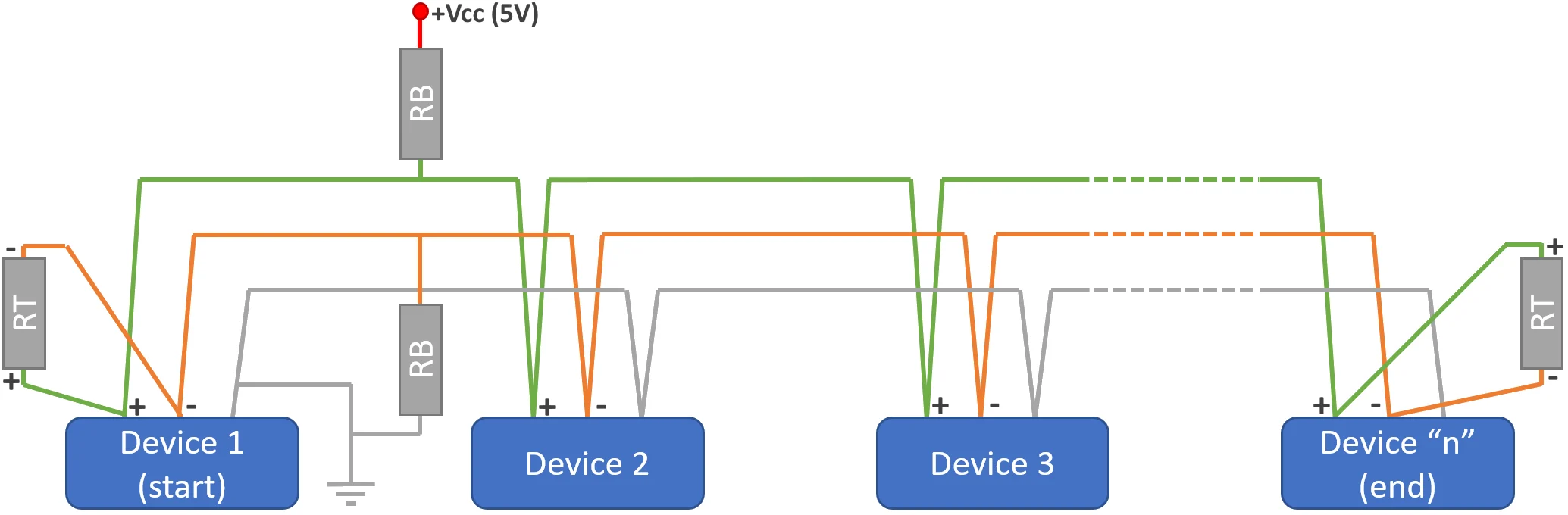
"RT" is the 120 Ω termination resistor.
"Device 1" on a Modbus network is the Master device initiating communication.
Bias Resistors
In an RS-485 network, there are periods when no device is actively transmitting. In a typical Modbus RTU master-slave system, this occurs after a slave has completed its response and before the master issues the next request.
During these idle periods, all transceivers release control of the bus and enter what is commonly referred to as a tri-state condition.
Without proper biasing, the two termination resistors at either end of the network cause the differential voltage between the A and B conductors to collapse towards 0 V. For many RS-485 receivers, this represents an undefined state. When presented with an undefined input, a receiver may interpret the signal incorrectly, generate false data transitions, or even oscillate between logic states.
The result can be a range of intermittent communication issues, including:
-
False start bits
-
Framing errors
-
Corrupted messages
-
Spurious data reception
-
Increased processor activity as controllers attempt to process non-existent traffic
To prevent this, RS-485 networks typically implement fail-safe biasing.
The purpose of fail-safe biasing is to ensure the bus remains in a known and stable idle state whenever no device is transmitting. This is achieved by creating a small, permanent differential voltage across the bus so that all receivers consistently interpret the network as being in a logic "mark" state when idle.
In its simplest form, network biasing is provided by a single pair of resistors located at one point on the bus, typically close to the master or primary controller:
-
A pull-up resistor connected between the positive data line and the supply voltage.
-
A pull-down resistor connected between the negative data line and signal ground.
Only one set of bias resistors should normally be fitted to a network. Multiple biasing locations can excessively load the bus and reduce signal integrity.
The schematic below illustrates a typical fail-safe biasing arrangement and how a stable idle-state voltage is maintained across the RS-485 network.
Step 8 – Reduce the Network
If the fault cannot be found immediately:
-
Disconnect half the devices.
-
Test.
-
Reconnect progressively.
This process quickly narrows the problem to:
-
A cable segment
-
A particular device
-
A local installation issue
The approach is often faster than lengthy protocol analysis.
Step 9 – Use an Oscilloscope if Available

A mustimeter can identify many installation issues.
An oscilloscope can identify the rest.
Typical indicators include:
-
Ringing
-
Reflections
-
Overshoot
-
Noise spikes
-
Collapsing differential voltage
A healthy RS-485 waveform should show:
-
Clean edges
-
Consistent amplitude
-
Minimal reflections
If significant ringing is visible, revisit topology and termination before investigating software.
Here is a good portable tried and tested oscilloscope:
2 Channel USB PC Oscilloscope with Arbitrary Waveform Generator - 10MHz - PICO TECHNOLOGY | CPC UK
Look for:
-
Reflections
-
Ringing
-
Distorted edges
-
Noise spikes
-
Differential voltage collapse
A healthy RS-485 waveform should have:
-
Clean transitions
-
Minimal overshoot
-
Consistent amplitude
If reflections are visible, suspect:
-
Incorrect topology
-
Incorrect termination
-
Excessive spur lengths
The Golden Rules for Reliable RS-485 Networks
Before commissioning any new installation:
✅ Daisy-chain topology
✅ Shielded twisted pair cable
✅ Two 120 Ω terminations only
✅ Termination at physical endpoints
✅ Single biasing location
✅ Common reference conductor
✅ Galvanic isolation where required
✅ Minimal stub lengths
✅ Separation from power cables
✅ Documented termination settings
✅ Documented biasing settings
✅ Consistent serial parameters
✅ Approximately 60 Ω measured across A/B with power removed
Step 10 – Only Now Look at Software
If the physical layer checks out, then move to protocol diagnostics.
Verify:
Serial Settings
All devices should match for:
-
Baud rate
-
Parity
-
Stop bits
-
Data bits
Device Addressing
Check for:
-
Duplicate Modbus addresses
-
Incorrect slave IDs
-
Devices replaced without reconfiguration
Modbus RTU Timing
Modbus RTU requires a silent gap between frames.
Problems can occur when:
-
Masters poll too aggressively
-
Gateways buffer traffic incorrectly
-
USB converters introduce timing anomalies
Error Counters
Where available, examine using Wire-Shark:
-
Lost packets
-
CRC errors
-
Per-device timeout counts
Errors concentrated on a particular device usually indicate a local wiring issue rather than a system-wide problem.
Key Takeaway
When an RS-485 network develops intermittent faults, start with the cable before the code.
Most communication problems can be traced back to one of five physical-layer issues:
-
Topology
-
Termination
-
Biasing
-
Common reference or isolation
-
Cable quality and routing
The vast majority can be diagnosed using nothing more than a multimeter, a wiring diagram, and careful inspection of the installation.
A correctly designed RS-485 network should run for years without intervention. When it doesn't, the answer is usually found in the physical layer long before it's found in the BMS or PLC program.
When an RS-485 network becomes unreliable, start with the cable, not the code.
Random CRC errors, intermittent timeouts, and devices that disappear without warning are usually symptoms of physical layer problems rather than protocol or software faults.
As a rule of thumb: if the wiring does not comply with RS-485 best practice, no amount of software debugging will make the network reliable.
Follow these guidelines, and your RS-485 network will provide years of reliable service!
Other Resources & Customer Survey:
💬 Don't miss out! Follow the Forest Rock News channel on WhatsApp Click Here!
💬 We’d also love your feedback! Please take a moment to complete our quick Customer Survey
It only takes a minute and helps us serve you better!

IoT Devices for BMS, Automation & Smart Connectivity | Forest Rock