

A Comprehensive Guide to Diagnosing and Resolving RS-485 Network Issues
Introduction
RS-485 is a robust industrial communication standard that allows multiple devices to communicate over long distances using differential signalling. Despite its reliability, network issues can still occur due to wiring problems, improper termination, device configuration errors, or environmental interference. This guide provides practical, field-tested techniques for diagnosing and resolving common RS-485 network problems.
Whether you're troubleshooting a BACnet MS/TP network, a Modbus RTU installation, or any other RS-485 based system, understanding the fundamental principles and having a systematic approach to fault-finding will save you time and frustration. This knowledge base article combines theoretical understanding with practical troubleshooting steps that seasoned BMS engineers use in the field every day.
Understanding RS-485 Fundamentals
What Makes RS-485 Different
RS-485 uses differential signalling, which means it transmits data using two wires where the voltage difference between them represents the data signal. This approach makes RS-485 remarkably resistant to electrical noise because any interference affects both wires equally and gets cancelled out when the receiver measures the voltage difference. This is why RS-485 can successfully operate in electrically noisy industrial environments where other communication methods would fail.
The standard supports multiple devices on a single bus, typically up to 32 without repeaters, though this can be extended to 256 devices using modern high-impedance transceivers. The network operates as a multi-drop bus where all devices share the same pair of wires, making it cost-effective for installations requiring many devices spread across significant distances.
Critical Network Requirements
Polarity Sensitivity
RS-485 is polarity-sensitive, meaning you must connect the positive wire (often labelled A, D+, or Data+) consistently across all devices, and likewise for the negative wire (B, D-, or Data-). Reversing the polarity at even a single device can cause communication failures for that device and potentially affect devices downstream on the network. Some older controller designs would actually power up with reversed polarity but render the network inoperative beyond that point, making this a critical first check during installation.
Characteristic Impedance and Termination
RS-485 networks require proper termination to prevent signal reflections. When electrical signals travel down a cable and reach the end, they can reflect back toward the source, similar to how ripples bounce off a wall in a pond. These reflections can interfere with the original signal and cause data corruption. To prevent this, termination resistors matching the cable's characteristic impedance (typically 120 ohms) must be installed at both far ends of the network. Think of these resistors as absorbing the signal energy, preventing it from bouncing back.
Pre-Testing Physical Inspection Checklist
Before reaching for your multi-meter, conducting a thorough physical inspection often reveals the problem immediately. Experience shows that a surprising number of RS-485 network issues stem from simple physical problems rather than complex electronic failures. Taking fifteen minutes for a methodical visual inspection can save hours of diagnostic work.
-
Verify Correct Wiring Polarity
Confirm that the MS/TP or Modbus RTU network wiring maintains consistent polarity throughout the entire installation. Check that terminal A connects to terminal A across all devices, and terminal B connects to terminal B. Use a visual inspection combined with continuity testing if polarity markings are unclear. Remember that different manufacturers may use different naming conventions (A/B, D+/D-, Data+/Data-), so consult device documentation to ensure proper connections.
-
Validate Device Addressing
Each device on an RS-485 network must have a unique address. Duplicate addresses will cause communication conflicts where two devices attempt to respond simultaneously, corrupting data transmission. Verify that all devices have properly configured addresses and that these addresses match your system documentation. Check both hardware DIP switches (on older devices) and software configuration settings (on newer devices).
-
Inspect All Connection Points
Examine every termination point along the network route for loose, corroded, or damaged connections. This includes screw terminals, punch-down blocks, and any intermediate junction boxes. Vibration from nearby equipment, thermal cycling, or poor initial installation can cause terminals to loosen over time. A connection that appears tight may actually have broken strands inside the wire insulation, creating intermittent contact that's difficult to diagnose.
-
Confirm Proper Power Supply
Verify that all devices receive power at the correct voltage levels specified by the manufacturer. A device operating outside its voltage specification may behave erratically or fail to communicate entirely. Check both that power supplies are functioning correctly and that voltage drops across long cable runs haven't reduced power below acceptable levels. Also verify power supply polarity, as mentioned earlier, since some legacy controllers would power up with reversed polarity but disable network communication.
Testing RS-485 Networks with a Multi-meter
A standard digital multi-meter provides valuable insight into RS-485 network health when you understand what to measure and how to interpret the results. While specialized RS-485 testers offer more features, a multi-meter allows you to perform effective diagnostics with equipment you likely already have available. The key is knowing which measurements matter and what the readings tell you about network condition.
Essential Voltage Measurements
Idle State Differential Voltage
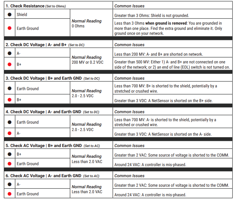
When no device is transmitting, measure the voltage difference between the A and B data lines. A healthy RS-485 network should show approximately 0 to 0.2 volts in the idle state. Some networks use biasing resistors that may create a small offset, but the differential voltage should remain stable and consistent. If you see large voltage swings or continuously changing values when the network should be idle, this indicates noise, improper termination, or a device stuck in transmit mode.
Active State Voltage Swing
During active communication, the differential voltage should swing between approximately +1.5V and -1.5V (or greater). If you observe communication activity but the voltage swing is less than 200 millivolts, this suggests cable problems, excessive loading from too many devices, or weak transmitter circuits. Higher voltage swings indicate stronger, more reliable signalling. You can trigger active communication by querying a device from your BMS or by using device-specific test functions.
Resistance Measurements
Important: Always disconnect power and all devices before making resistance measurements. Measuring resistance on a powered circuit can damage your multi-meter and provide inaccurate readings.
Cable Characteristic Impedance
Measure the resistance between the A and B lines with all devices disconnected and termination resistors removed. For a properly installed twisted-pair cable, you should see very high resistance (megohms) between the data lines, indicating good insulation and no short circuits. A low resistance reading here suggests damaged cable insulation or moisture intrusion.
Termination Verification
With termination resistors installed at both ends of the network but all devices disconnected, measure the total resistance between A and B. You should read approximately 60 ohms, which represents the two 120-ohm termination resistors in parallel. A reading significantly different from 60 ohms indicates missing, incorrect, or too many termination resistors. This measurement helps you verify that termination exists and that nobody has accidentally installed termination at intermediate points along the network.
Isolation Testing
When facing persistent problems, systematically isolating network segments helps pinpoint the problematic area. Disconnect half the network and test if communication improves. If the problem disappears, the issue lies in the disconnected segment. If the problem persists, it's in the remaining segment. Continue subdividing until you isolate the specific device or cable run causing the issue. This binary search approach efficiently narrows down problems even in large networks.
Modbus RTU Specific Troubleshooting
Modbus RTU implementations over RS-485 present specific challenges because the protocol defines strict timing requirements and message framing. A 'no response from slave' error is particularly frustrating because it provides no information about where in the communication chain the failure occurs. The slave device might not be receiving messages, might be receiving corrupted messages, or might be responding but having those responses corrupted before reaching the master.
Initial Configuration Verification
-
Communication Parameters Match
Verify that the baud rate, data bits, parity, and stop bits settings match exactly between the master and all slave devices. Modbus RTU commonly uses 9600 or 19200 baud, 8 data bits, no parity, and 1 stop bit (8-N-1), but variations exist. A mismatch in any parameter prevents successful communication. Also confirm that the character timeout and frame delay settings meet Modbus RTU specification requirements, typically 3.5 character times for message framing.
-
Slave Address Assignment
Confirm that the slave address configured in the device exactly matches the address the data logger or master uses in its queries. Modbus RTU supports addresses 1-247 (address 0 is reserved for broadcast messages). A simple addressing error is surprisingly common during initial setup. Double-check both the device configuration and your polling software configuration.
-
Physical Layer Integrity
Review all physical wiring connections as described in the pre-testing checklist. Experience shows that approximately eighty percent of Modbus RTU communication failures stem from wiring issues rather than configuration problems. Pay particular attention to polarity, as reversed connections are the single most common cause of no-response errors.
Advanced Diagnostic Steps
If basic checks don't resolve the issue, these advanced diagnostic techniques help identify more subtle problems that prevent reliable Modbus RTU communication.
Polarity Swap Test
When uncertain about polarity correctness, try swapping the A and B connections at the master device while keeping all slave connections unchanged. If communication suddenly begins working, the entire network had reversed polarity. While this quick test violates proper engineering practice, it provides immediate confirmation and saves diagnostic time in troubleshooting situations.
Incremental Device Addition
Start with only the master and a single slave device. Once this minimal configuration communicates successfully, add one device at a time, testing after each addition. This methodical approach quickly identifies which device or network segment introduces the problem. If the network fails after adding a specific device, that device either has configuration issues, is faulty, or creates electrical loading that exceeds network capacity.
Proper Cable Selection and Installation
Cable quality dramatically affects RS-485 network reliability, yet it's tempting to use whatever cable is readily available to save time or money. This section explains why proper cable selection matters and what happens when you compromise on cable quality.
Why Specialised RS-485 Cable Matters
Using random electrical wire instead of proper twisted-pair data cable creates several problems that may not appear immediately but will cause reliability issues over time. RS-485 cable uses a specific 120-ohm characteristic impedance achieved through precise conductor geometry and insulation properties. Standard electrical wire has unknown and inconsistent impedance, causing signal reflections and degradation.
The twisting of the wire pairs serves a crucial function. When electromagnetic interference induces noise into the cable, the twisting ensures that both conductors receive nearly identical interference. Since RS-485 receivers measure the difference between the two wires, this common-mode interference gets cancelled out. Untwisted pairs don't provide this cancellation, making them susceptible to noise pickup.
Recommended Cable Specifications
Standard Recommendation: Use shielded twisted-pair cable such as Belden 9841 (single pair) or Belden 9842 (dual pair) with 120-ohm characteristic impedance. These cables include a foil or braided shield that provides additional protection against electromagnetic interference, particularly valuable in industrial environments with variable frequency drives, motors, and other noise sources.
The wire gauge typically ranges from 22 AWG to 24 AWG. The specific gauge number matters less than understanding that you need to minimize both resistance and capacitance in the cable. Resistance causes voltage drop and signal attenuation, while capacitance limits the maximum achievable baud rate. Longer networks require larger gauge wire (smaller AWG numbers) to keep resistance acceptable.
Shielding provides little benefit for short runs on a test bench with no nearby electrical equipment, but its value increases dramatically as cable length grows and as the installation environment becomes noisier. In industrial settings, always use shielded cable and connect the shield to earth ground at one end only (typically at the master device) to prevent ground loops while still providing noise protection.
Network Topology Best Practices
The physical layout of your RS-485 network significantly impacts its reliability and performance. While RS-485 supports various topologies in theory, practical experience shows that some configurations work much better than others in real-world installations.
Daisy-Chain Bus Configuration
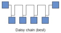
The daisy-chain bus represents the ideal RS-485 topology. In this configuration, cable runs continuously from the master to the first device, then from the first device to the second device, and so on until reaching the final device. This creates a single continuous transmission line without branches or stubs. Termination resistors install only at the two far ends, the master and the last device on the chain.
This topology minimises signal reflections because the electrical signal travels down a continuous impedance-controlled path. Any branches or stubs create impedance discontinuities that reflect signal energy back toward the source, potentially causing data corruption. While small stubs under a few inches may work in low-speed networks, following strict daisy-chain topology eliminates an entire class of potential problems.
Why Star and Stub Topologies Fail
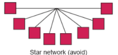
A star topology where multiple devices connect to a central point works well for Ethernet but creates severe problems for RS-485. Each branch from the central point creates a stub that reflects signals back toward the source. These reflections arrive at different times depending on stub length, creating a complex interference pattern that corrupts data transmission.
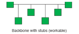
Similarly, adding tee connections or stubs anywhere along a daisy-chain network introduces the same reflection problems. The RS-485 specification technically allows short stubs, but 'short' means less than one-twentieth of a wavelength at the network's highest frequency component. At typical Modbus speeds, this works out to just a few inches. Rather than calculating acceptable stub lengths, simply avoid stubs entirely by routing cable in a true daisy-chain configuration.
Cable Routing Considerations
Critical: Never route RS-485 communication cables in the same conduit or cable tray as power cables. Power cables carrying high currents, especially those feeding variable frequency drives or other switching loads, generate electromagnetic interference that can couple into communication cables even through shielding. Maintain at least twelve inches of separation between communication and power cables wherever possible.
When cable routing requires crossing power conductors, do so at a ninety-degree angle to minimize the length of parallel run and reduce coupling. Never run communication cables parallel to power cables for extended distances. If your installation requires running both power and communication in the same general area, use separate raceways and keep them physically separated.
Understanding and Implementing Termination
Termination resistors prevent signal reflections that would otherwise corrupt data transmission. Many RS-485 networks appear to work without proper termination, especially short networks at lower baud rates, but this represents a reliability risk. As network length increases, baud rate increases, or as electrical noise worsens, unterminated networks that worked initially will begin experiencing intermittent communication failures that prove difficult to diagnose.
How Termination Works
When an electrical signal travels down a transmission line and reaches the end, the signal energy must go somewhere. If the line simply ends (open circuit), the energy reflects back toward the source, creating a voltage spike at the end of the line. This reflected signal travels back along the line, potentially interfering with new data transmission.
A termination resistor matched to the cable's characteristic impedance absorbs this signal energy, converting it to heat and preventing reflection. For standard 120-ohm RS-485 cable, this means installing a 120-ohm resistor between the A and B data lines at each end of the network. The resistor should be rated for at least one-quarter watt to handle the power dissipation, though larger wattage ratings provide an additional safety margin.
Proper Termination Placement
Only at the Far Ends
Install termination resistors only at the two farthest ends of the network - nowhere else. Many RS-485 devices include internal termination resistors that can be enabled via switches or jumpers. Enable termination only at the master device and the last device on the chain. All intermediate devices must have their termination disabled.
Installing termination at intermediate points creates multiple impedance discontinuities and doesn't properly absorb signal reflections. If you measure 60 ohms across the network (as described in the multi-meter testing section) but communication fails, check whether someone inadvertently enabled termination at an intermediate device. This is a common mistake during installation when technicians enable termination switches without understanding where termination should actually be located.
Practical Verification: After installation, measure the resistance between A and B with all devices connected but powered off. You should read approximately 60 ohms, representing the two 120-ohm termination resistors in parallel. If you read 120 ohms, only one end has termination. If you read 40 ohms or less, too many devices have termination enabled. If you read very high resistance (megohms), no termination exists.
Multiple Master Considerations
The Modbus RTU protocol specification defines a single-master, multiple-slave architecture. This means the network should have exactly one device that initiates communication (the master), with all other devices responding only when queried (the slaves). This architecture prevents communication collisions because only the master decides when to transmit.
Adding a second master device to the network creates a fundamental problem: both masters may attempt to transmit simultaneously, causing data collision and corruption. Neither master knows when the other master is transmitting, so they cannot coordinate their communication. While specialized equipment like bus arbitrators, token-passing controllers, or multiple RS-485 networks can enable multiple-master architectures, these require additional complexity and careful configuration.
Important: If your application requires multiple systems to access the same RS-485 network, do not simply connect two masters to the same bus. Instead, consider using a single master that can be accessed by both systems (through a gateway or data sharing mechanism), or implement separate RS-485 networks for each master, or investigate specialized multi-master protocols and hardware designed for this purpose.
Systematic Troubleshooting Approach
When facing a non-communicating RS-485 network, following a systematic diagnostic process saves time and prevents overlooking simple problems. The tendency under pressure is to jump to complex theories about electrical interference or protocol timing issues, but experience shows that fundamental problems like wiring errors or loose connections cause the vast majority of failures.
Progressive Build-Up Method
Start with the absolute minimum configuration: just the master and one slave device. Use short cable runs and ensure this minimal system communicates successfully before adding complexity. Verify that both devices have correct power, proper configuration, and that the physical connection uses proper cable with correct polarity.
Once the minimal system works, add one additional device at a time. After each addition, test communication to all devices. If communication fails after adding a specific device, you immediately know where to focus your troubleshooting efforts. This methodical approach prevents the overwhelming situation where nothing works and you have no idea which of many possible problems is preventing communication.
Debugging Advantage: Building the network incrementally makes debugging much easier. When you add device number seven and suddenly devices one through six stop responding, you know device seven has a problem, possibly a short circuit, enabled termination at an intermediate point, incorrect address causing conflicts, or excessive electrical loading. Isolating the problematic device immediately focuses your troubleshooting.
Documentation and Organisation
Maintain clear documentation of device addresses, termination settings, and network topology. When troubleshooting under deadline pressure with contractors waiting for system commissioning, having accurate documentation prevents time-wasting confusion. Document which end devices have termination enabled, record all device addresses in a central location, and create a simple diagram showing the physical daisy-chain sequence.
Label cables at both ends, especially in installations with many cables running through the same raceways. Nothing wastes more time than tracing cables through conduit trying to identify which cable connects to which device. Simple labels applied during installation save hours during troubleshooting and future maintenance.
Common Mistakes and How to Avoid Them
Learning from common mistakes helps you avoid repeating them. These errors represent the most frequent problems encountered in real-world RS-485 installations, compiled from years of troubleshooting experience across diverse industrial and building automation systems.
Installation Errors
-
Using Non-Specified Cable
Installing whatever cable is available rather than proper 120-ohm twisted-pair creates intermittent problems that appear later. The network may work initially in the test lab but fail when installed in a noisier environment or when extended to full length. Always use specified cable types, especially for permanent installations. The cost difference between proper cable and random wire is minimal compared to the cost of troubleshooting and rework.
-
Star or Stub Topology
Creating star configurations or adding tees along the network to simplify installation routing may seem convenient but causes signal reflection problems. While you might get away with this in very short, low-speed networks, it creates a reliability risk. Take the time to route cable in a true daisy-chain configuration. The installation effort pays off in reliable long-term operation.
-
Incorrect or Missing Termination
Either forgetting to enable termination at the network ends or enabling it at intermediate devices causes problems. Verify termination placement carefully during installation. Use the resistance measurement technique described earlier to confirm that exactly two termination resistors are properly installed at the network ends and nowhere else. Check whether intermediate devices have DIP switches or jumpers that might inadvertently enable termination.
Configuration Errors
-
Mismatched Communication Parameters
Assuming devices share the same baud rate, parity, or stop bit configuration without verification causes communication failures. Create a configuration checklist and verify each device systematically. Many devices have tiny displays or obscure menu systems that make configuration verification tedious, but skipping this step leads to frustrating troubleshooting sessions where everything appears correct but nothing communicates.
-
Duplicate or Incorrect Addresses
Failing to verify unique device addresses leads to conflicts and corrupted responses. Maintain an address allocation table and verify each device against this table. When adding new devices to an existing network, check that the proposed address isn't already in use. Some devices come with default addresses that you must change; forgetting this step causes duplicate address conflicts.
-
Reversed Polarity
Connecting A to B and B to A at even a single device prevents that device from communicating and may affect devices downstream. The most insidious version of this error involves reversed polarity at the master, meaning the entire network has reversed polarity relative to standard convention but appears internally consistent. Always verify polarity carefully, especially when different cable manufacturers use different colour codes or labeling conventions.
Conclusion
Successful RS-485 network troubleshooting combines theoretical knowledge with practical diagnostic skills and systematic problem-solving approaches. While sophisticated test equipment can help, a solid understanding of RS-485 fundamentals combined with basic tools like a multi-meter allows you to diagnose and resolve most network problems effectively.
Remember that the majority of RS-485 problems stem from simple physical issues - wiring errors, loose connections, improper termination, or configuration mistakes - rather than complex electronic failures. Starting with basic physical inspection and working methodically through diagnostic steps saves time and prevents overlooking obvious problems while searching for obscure causes.
Experience shows that taking time during installation to use proper cable, follow correct topology, verify configuration settings, and document the network thoroughly prevents most troubleshooting situations from occurring in the first place. The pressure to complete installations quickly often leads to shortcuts that create reliability problems requiring many more hours to diagnose and correct than would have been required to do the installation properly initially.
Quick Reference Guide
Critical Specifications
|
Parameter |
Specification |
|
Cable Impedance |
120 ohms characteristic impedance |
|
Termination |
120 ohm, 1/4 watt or greater resistor at each end only |
|
Total Resistance |
60 ohms between A and B with termination installed |
|
Recommended Cable |
Belden 9841 (single pair) or 9842 (dual pair), shielded twisted-pair |
|
Maximum Devices |
32 standard loads, up to 256 with high-impedance transceivers |
|
Idle Voltage |
0 to 0.2V differential (A minus B) when network idle |
|
Active Voltage |
±1.5V minimum differential swing during communication |
Pre-Deployment Checklist
-
Verify cable is proper 120-ohm shielded twisted-pair
-
Confirm daisy-chain topology with no stars or stubs
-
Check termination enabled only at far ends (measure 60 ohms total)
-
Verify consistent polarity across all devices
-
Confirm unique device addresses with no duplicates
-
Verify matching communication parameters (baud, parity, stop bits)
-
Check proper power supply to all devices
-
Maintain separation from power cables (minimum 12 inches)
-
Document network configuration and device addresses
-
Test incrementally, adding one device at a time
Troubleshooting Decision Tree
No Communication at All
-
Check power to all devices
-
Verify cable connections and polarity
-
Measure voltage between A and B (should see differential)
-
Try polarity swap test at master
Intermittent Communication
-
Check for loose connections and broken wires
-
Verify proper termination (measure 60 ohms)
-
Check for electrical noise sources nearby
-
Verify shield grounding (one end only)
Some Devices Don't Respond
-
Verify device addresses match configuration
-
Check communication parameters on non-responding devices
-
Isolate network to test problematic devices individually
-
Check for enabled termination at intermediate devices
Other Resources & Customer Survey:
💬 Don't miss out! Follow the Forest Rock News channel on WhatsApp Click Here!
💬 We’d also love your feedback! Please take a moment to complete our quick Customer Survey
It only takes a minute and helps us serve you better!

IoT Devices for BMS, Automation & Smart Connectivity | Forest Rock