

Forest Rock Customer Knowledge Base
Overview
Wattsense gateways make it easy to bring LoRaWAN sensors into your Building Management System.
Whether you’re using a Wattsense Tower (cloud‑connected) or a Wattsense Bridge (local server deployment), the architecture follows the same core principles:
-
Sensors send data using LoRaWAN
-
The gateway decodes the messages locally
-
Data is routed either to the Wattsense backend (Tower) or to your local server (Bridge)
This article explains how the communication flow works and the role of each component.
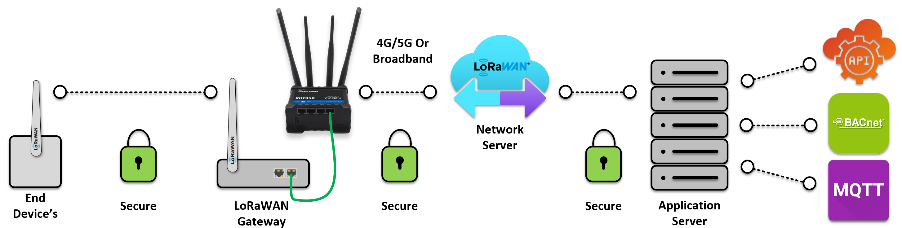
1. How LoRaWAN Communication Works
Step 1 – Sensor Joins the Network
When a LoRaWAN sensor first powers up, it performs a JOIN request.
This securely pairs the device with the Wattsense gateway.
Step 2 – Sensor Sends Data
Once joined, the sensor begins sending uplink messages using the LoRaWAN protocol.
These may include:
-
Temperature
-
Humidity
-
CO₂
-
Occupancy
-
Pulse counts
-
TRV status, etc.
Step 3 – Gateway Decodes the Message
Every Wattsense Tower and Bridge includes a built‑in LoRaWAN Network Server (LNS).
This means:
-
LoRa messages are decoded locally, not in the cloud
-
Payloads are translated into meaningful data before leaving the gateway
-
You avoid external LoRaWAN servers or third‑party routing
Step 4 – Data Is Forwarded to the Correct Destination
Depending on the device type:
-
Tower → sends decoded data to the Wattsense Cloud backend
-
Bridge → sends decoded data to your local server (no external connection required)
This keeps the system lightweight, secure, and easy to integrate with Niagara, BACnet, or Modbus.
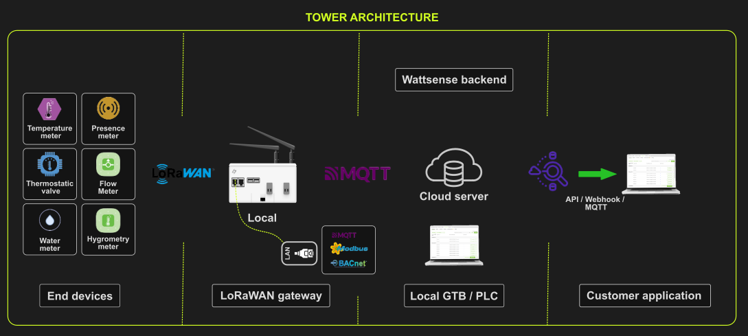
2. Wattsense LoRaWAN Architecture
Wattsense Tower Architecture
(Cloud‑connected)
📡 End Devices → Tower → Wattsense Cloud → Your BMS
Typical use cases:
-
Multi‑site deployments
-
No local server required
-
Managed from the Wattsense Web App
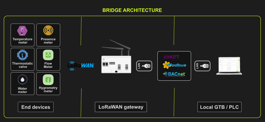
Wattsense Bridge Architecture
(Local server deployment)
📡 End Devices → Bridge → Local Server → Your BMS
Typical use cases:
-
On‑premise networks
-
Environments with strict IT/security policies
-
Sites without guaranteed internet access
3. Key Components Explained
End Devices (LoRaWAN Sensors & Actuators)
These are battery‑powered devices that:
-
Send uplink data wirelessly to the gateway
-
Receive downlink commands when needed (e.g., TRVs, relays)
Examples: environmental sensors, TRVs, water meters, door contacts.
Wattsense LoRaWAN Gateway (Tower or Bridge)
The gateway:
-
Listens for LoRaWAN messages
-
Authenticates and manages JOIN requests
-
Decodes payloads locally via its built‑in LNS
-
Forwards decoded values to either the cloud (Tower) or a local server (Bridge)
It eliminates the complexity of running a separate LoRaWAN Network Server.
4. Summary
Wattsense simplifies LoRaWAN integration by embedding all required LoRaWAN network functionality directly into the gateway. This means:
-
No external LoRaWAN servers
-
Easy commissioning
-
Fast sensor onboarding
-
Secure and predictable data routing
-
Seamless integration with Niagara and other BMS platforms
Whether you choose the Tower or the Bridge, the communication flow remains clear, reliable, and optimised for building applications.