

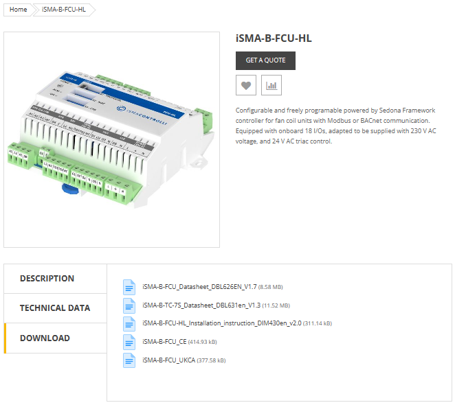
Here's the hardware manual:
Just navigate to the link below the picture and select Download to choose the manual you need.
-
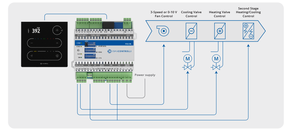
If you look at page 13 you'll see the full wiring diagram for each type of display.
-
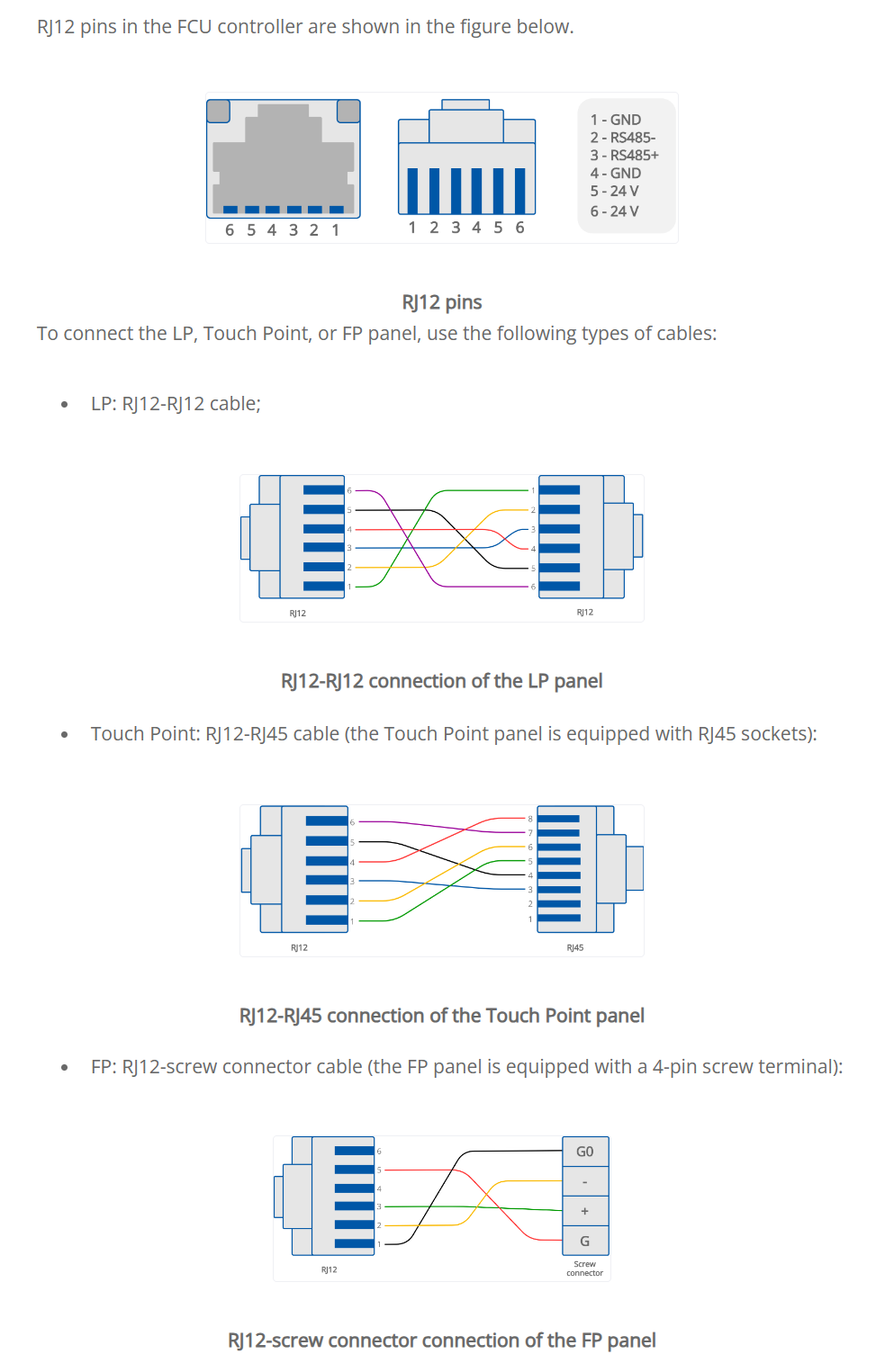
If you have the touchpoint you'll see it needs to be the RJ12-RJ45.
The diagram below shows the cable going from the first RJ12 socket to the touchpoint display.
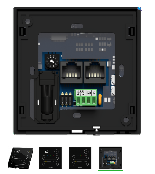
RJ12 Socket for External Connections (ismacontrolli.com)
RJ12 Socket for External Connections
The RJ12 socket is designed for connecting external modules, Modbus devices, and room/wall panels. The FCU device has two parallel RJ12 sockets (RS485 interface in a switch mode) with the same pin configuration. These sockets provide communication in the Modbus RTU protocol.
The RJ12 socket provides a power supply dedicated for external room panels with maximum load up to 2.5 W per both sockets. Before connecting devices powered from RJ12, please calculate the power supply load. For example, the power consumption of the LP/Touch Point panels with a temperature sensor, on average, is 0.5 W, so the maximum number of such panels on the bus is 5, while the average power consumption of the FP panels is 0.2 W, so the maximum number of such panels on the bus is 10. It is recommended to connect maximum 5 LP/Touch Point panels working at the same time or 10 FP panels.
Worth to notice:
Connected panels can be freely combined (5 LP panels, or 5 Touch Point panels, or 2 LP panels and 3 Touch Point panels, or 3 Touch Point panels and 5 FP panels etc.). It is important not to exceed a maximum load of 2.5 W for both RJ12 sockets together.
For short distance, up to 100 m, it is recommended to use for connection a standard category 3-, 4-, or 6-wire telephone straight cable without crossing (for example, YTLYP 6x0.12). For longer distance, it is recommended to use a standard twisted shielded Modbus cable.
RS485
There are 3 communication protocols that can be selected using the DIP switch 2 and PROTOCOL field
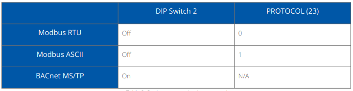
The Modbus register reading the protocol set on the DIP switch is the following: PROTOCOL_DIPSWITCH: reads the communication protocol set on the DIP switch; Modbus register: 30003; BACnet object: N/A.
Setting MAC Address
The device's MAC address can be set using one of the following methods:
-
Rotary switch: sets addresses from 1-9
-
If 0: ADDRESS (decimal address: 22).
-
The Modbus register reading the address set on the rotary switch is the following: ADDRESS_ROTARY_SWITCH: reads the Modbus address set on the rotary switch (0 means the address is read from the ADDRESS register/object)
-
Modbus register: 30002; BACnet object: N/A.
There are a few confusing points to explain
The first thing that might throw you is that the customer might be talking about a touch screen,
so you might assume that they mean one of the full iSMA android screens.
So its best to ask the question and clarify what they have first of all.
It might well be a touch panel they are talking about (iSMA TouchPoint) to control temp etc.
Also tracking down the wiring wasn't easy.
It's a strange setup where the manual suggests that the engineer needs to manually wire an RJ12 to RJ45 connector as shown in the diagram.
RJ12 Socket for External Connections (ismacontrolli.com)
May be possible to buy a premade cable for this.
All diagrams were taken from the ISMA-B-FCU
QuickStart and hardware manuals available from support.gc5.pl
Engineers can manually make up and wire an RJ11 to RJ45 connector as shown in the diagram above for the display you have purchased.
If like I used to be you are rubbish at making up the connections, here is a Top Tip
You can purchase special Pass Through Connectors, Cat5e RJ45 and RJ12
The instructions below show how simple it is to wire up the connector with a 99.99% success rate.
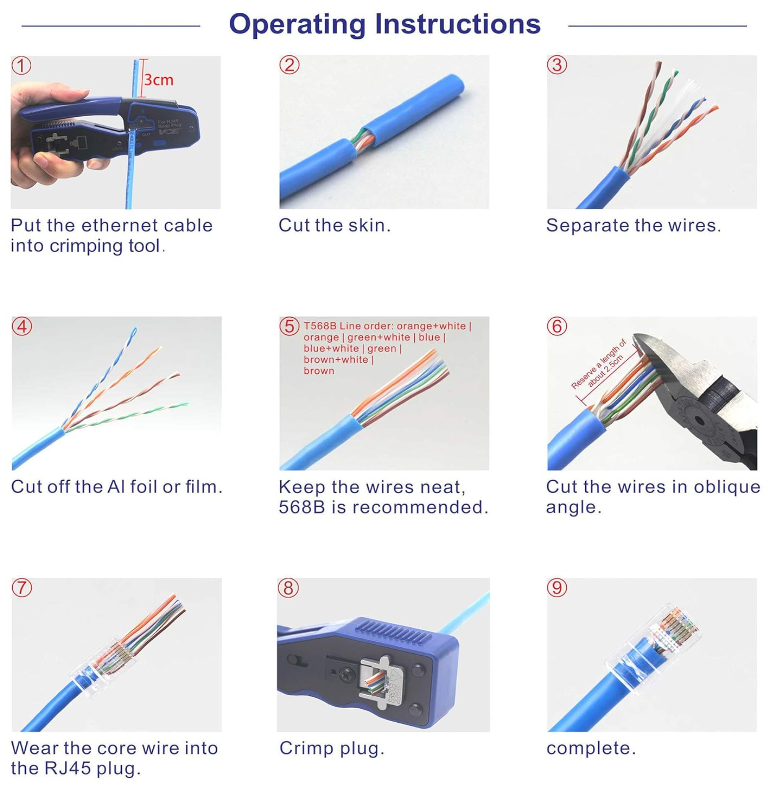
My crimping tool of choice is from Klein Tools

Klein RJ45 CAT6 Pass Thru Modular Data Plug (Pack of 50) available from CEF
RJ12 6P4C Pass Through Connectors are available online
We currently do not appear to sell the cable on our own web shop but that is something we can look into further down the line…..
Other Resources & Customer Survey:
💬 Don't miss out! Follow the Forest Rock News channel on WhatsApp Click Here!
💬 We’d also love your feedback! Please take a moment to complete our quick Customer Survey
It only takes a minute and helps us serve you better!

IoT Devices for BMS, Automation & Smart Connectivity | Forest Rock