

NOTE: All iSMA Universal Inputs cannot read a 4-20mA signal directly, so to read a 4-20mA sensor you will find in the box of every iSMA device (with Universal Inputs) a set of 200 Ohm resistors.
"It is extremely simple to measure 0-20 mA analog signal from a sensor with a JACE IO expansion card that will measure only voltage inputs." or similar
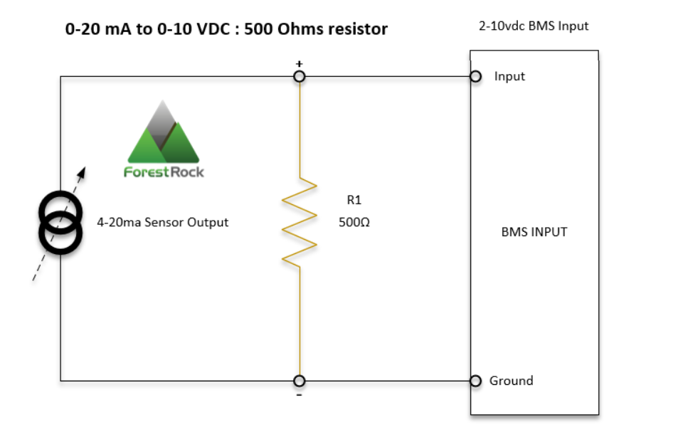
A JACE voltage input accepts a 0-10 V signal, but may not accept a 0-20mA signal directly.
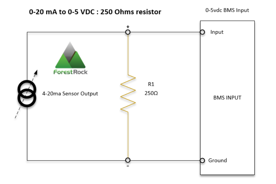
Basically, Ohms law states that voltage(V) is equal to the current(I) multiplied by the resistance(R) which is used to calculate a resistor value in order to convert the 0-20mAsignal to a voltage.
Voltage (V) = Current (I) x Resistance (R)
A Note Why 250 Ω or 200 Ω May Be Better:
These ranges sit comfortably within the controller’s 0–10 V input, so there is:
-
No loss of signal at the low end.
-
The controller can scale the full 4–20 mA range without clipping.
-
Resolution is lower (e.g., 250 Ω gives 0.25 V per mA), but the entire sensor range is preserved, which is more important for accurate control.
How it would look wired to the iSMA connection at terminals of the controller
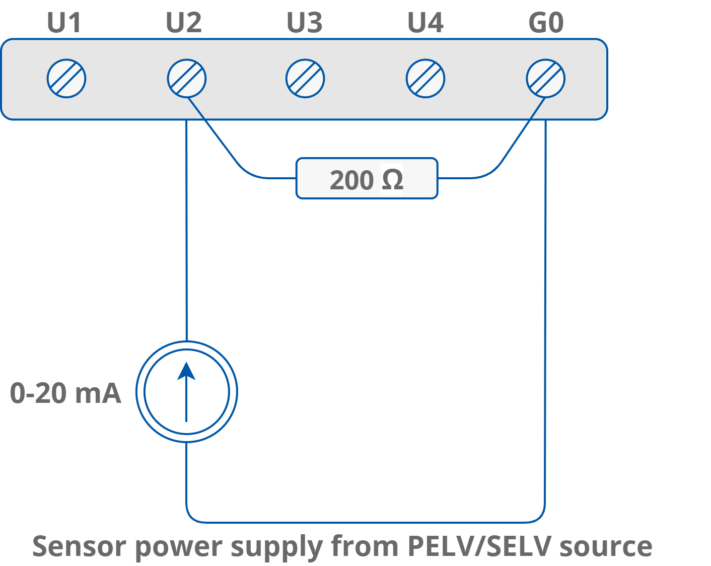
The resistors supplied will convert the Current (mA) into a readable Voltage for the inputs:
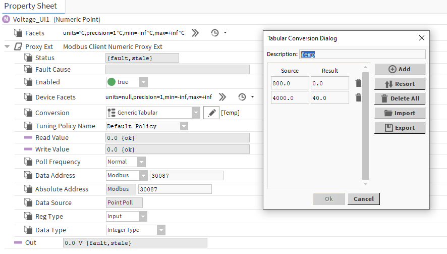
4 mA will translate to 800 mV (0.8V) – 4mA*200Ohm=800mV
20 mA will translate to 4000 mV (4V) – 20mA*200Ohm=4000mV
The scaling from Volts to temperature/humidity/CO2/pressure (depending on the sensor that it is connected to) will need to be made in the BMS controller.
In the following example, we have converted the linear signal from a 4-20mA temperature sensor into degC. The iSMA modules are reading mV which is why we have filled the Source field with mV values.
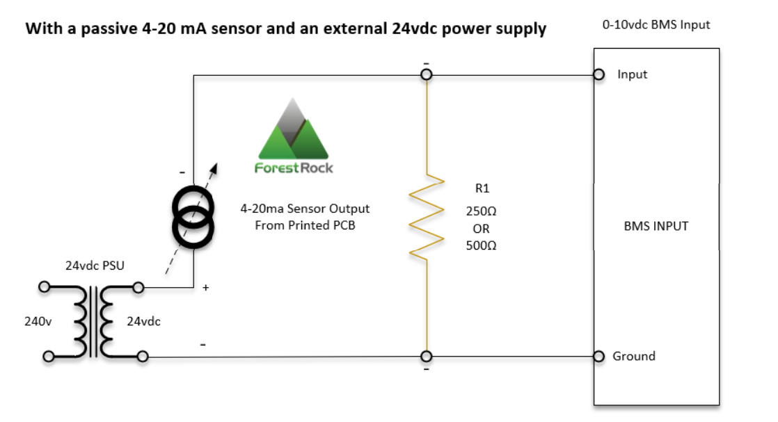
In case you want to read a sensor that has only 2 wire connections for both powering and signal, it is possible to connect it as shown in the picture below. You must remember that G0 from the Power Supply has an inside connection to G0 in Universal Inputs in all iSMA Modules, so you can use the same power supply for device and sensor if the sensor requires a 24 V power supply.
What is a 4-20 mA current loop?
The 4-20 mA current loop has been the standard for signal transmission and electronic control in industrial process control systems since the 1950’s.
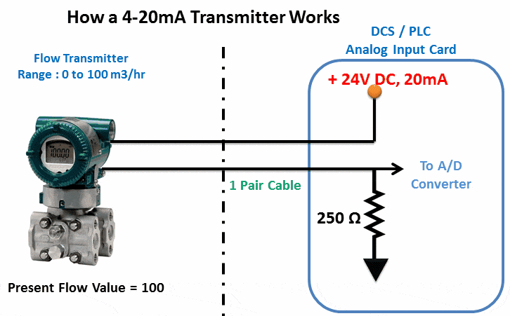
The 4 mA to 20 mA current loop is a common method of transmitting sensor information in many industrial process monitoring applications—typically in systems monitoring pressure, temperature, pH, flow, or other physical factors. These systems employ a two-wire, 4 mA to 20 mA current loop, in which a single twisted-pair cable supplies power to a transmitter and also carries the output signal.
In a current loop, the current signal is drawn from a dc power supply, flows through the transmitter, into the controller, and then back to the power supply in a series circuit. The advantage is that the current value does not degrade over long distances, so the current signal remains constant through all components in the loop. As a result, the accuracy of the signal is not affected by a voltage drop in the interconnecting wiring.
Voltage drop
Voltage signals sent over a long distance will, however, degrade in accuracy and develop a voltage drop (using Ohm’s Law) proportional to the length of the cable. Accuracy loss of the voltage signal would equal the mA signal value multiplied by the resistance of the wire.
The use of 4 mA as a “Live Zero” enhances the signal-to-noise-ratio at low levels. This Live Zero also makes a loop failure more apparent. A nonfunctioning current loop with an open termination or connection has zero current flow, which is outside the valid 4 to 20 mA signal range.
Verifying the 4 to 20 mA loop
Milliamp loop calibrators are typically used to test loops that measure pH, pressure, temperature, level, and flow. Verifying the 4 to 20 mA loop is a crucial step in any instrument calibration. Full loop verification includes testing the output of the transmitter, the wiring, input to the control system as well as the control system input card and the return wiring back to the transmitter.
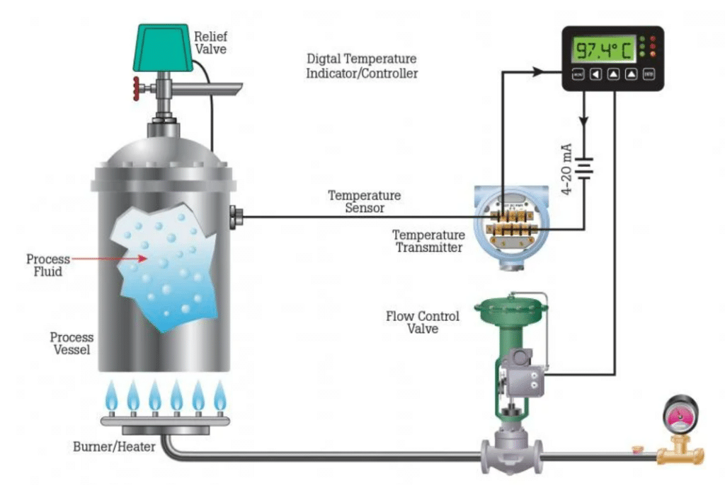
The loop’s operation is straightforward: a sensor’s output voltage is first converted to a proportional current, with 4 mA normally representing the sensor’s zero-level output and 20 mA representing the sensor’s full-scale output. A reading of 20 mA means that a direct-acting valve, for example, is 100% open, and a reading of 4 mA means that it is closed. (The opposite is true for a reverse-acting valve). Readings between the maximum and minimum values indicate that the circuit is controlling the valve.
Verifying a 4-20 mA loop is a crucial step in both troubleshooting and calibrating process systems. Full verification includes testing the output of the transmitter, the wiring, input to the control system and control system input card, and the return wiring back to the transmitter.
The functions of an advanced loop calibrator allow technicians to troubleshoot on the spot without disconnecting wires or “breaking the loop.” Multifunction process calibrators can also be used to test 4-20mA loops as well as digital controls.
To measure a 4-20 mA loop signal with a process clamp meter:
-
Access the signal wires (typically by removing the cover on the transmitter).
-
Locate the mA signal and zero the mA clamp meter
-
Verify the mA measurement, which should be between 4 and 20 mA
-
This measurement technique does not interrupt (break) the loop to measure the 4 to 20 mA signal
To measure a 4-20 mA loop signal with a multimeter or loop calibrator:
-
Check with operations before initiating the measurement
-
Access the signal wires (typically by removing the cover on the transmitter).
-
Select the mA dc measurement function and connect the test leads for the mA measure
-
Locate the mA signal wire, disconnect one lead of the signal wire and put the meter in series with the mA signal wire, and view the mA measurement
-
This measurement technique interrupts (breaks) the loop to make the 4 to 20 mA measurement
Other Resources & Customer Survey:
💬 Don't miss out! Follow the Forest Rock News channel on WhatsApp Click Here!
💬 We’d also love your feedback! Please take a moment to complete our quick Customer Survey
It only takes a minute and helps us serve you better!

IoT Devices for BMS, Automation & Smart Connectivity | Forest Rock