

A Practical Guide for HVAC Engineers
Understanding 3-Wire Actuators, Voltage Logic, and Virtual Position Tracking
What This Guide Covers
Raise/lower actuators (also called 3-wire or reversible actuators) are common in HVAC, but controlling them through Niagara's RaiseLower component confuses many engineers. This guide explains:
● The fundamental difference between 0-10V modulating valves and raise/lower actuators
● Why the voltage logic works the way it does (0V, 4V, 7V, 10V)
● How to wire actuators to TRIAC outputs correctly
● Virtual position tracking and why it matters
● Common mistakes and how to avoid them
● Troubleshooting when valves won't move
● How to identify valve types during site surveys
For Site Surveyors: Identifying Valve and Actuator Types
Before you can design a BMS upgrade, you need to know what's already on site. Here's how to identify what type of valve control you're dealing with.
Quick Identification Method: Count the Wires
Look at the actuator mounted on the valve. How many electrical wires go to it?
4 wires (24v Plus Grd & Signal): Modulating actuator (0-10V analog control). You'll see typically a thin cable with 4 or 5 cores. Two cores will be the power usually red and black the two signal cables 0-10v signal and the ground, the cable colours may vary, and sometimes a 5th wire which could be the 0-10v position feedback signal.
3 wires: Raise/Lower actuator (3-wire, 2-point control). Usually heavier gauge wires because they carry power to the motor usually 24v or 240v.
Common Manufacturers and Their Labeling
Belimo Actuators (Most Common in UK)
Modulating (0-10V):
● Model numbers contain 'LM' (Linear Modulating)
● Examples: LMB24, LM24A, LM230A, LMCB24
● Label shows: '0-10V' or 'DC 0...10V'
● Wire colors: Usually brown/white (or red/black) for signal, green/yellow for ground
● Physical appearance: Smaller, lighter actuators. Often have a manual override knob or button.
Raise/Lower (3-wire):
● Model numbers contain 'SM' (Spring Return) or 'NM' (Non-Spring Return)
● Examples: SM24A, SM230A, NM24A, NM230A
● Label shows: '3-point' or 'Open-Close' or 'Y1-Y2'
● Wire colors: Typically black (common), brown (open/raise), blue (close/lower)
● Physical appearance: Bulkier, heavier. You can often hear the motor running when it operates.
● Key giveaway: Look for 'running time' on the label (e.g., '90s', '120s') - this is drive time, only present on raise/lower actuators.
Satchwell/Invensys Actuators (Common in Older UK Installations)
Modulating (0-10V):
● Model series: SDE (e.g., SDE31, SDE61)
● Label typically shows 'Modulating' or '0-10V'
● Usually smaller, square-ish body with 2-wire cable
Raise/Lower (3-wire):
● Model series: SDA, SQM, SQS (e.g., SDA71, SQM40, SQS31)
● Label shows 'Spring Return', 'Fail Safe', or '2-position'
● Larger cylindrical or rectangular body
● Running time is usually marked on the label (common values: 60s, 90s, 120s, 150s)
Honeywell Actuators
Modulating (0-10V):
● Model series: ML (e.g., ML6420, ML7420, ML6421)
● Label shows 'Proportional' or '0-10VDC'
Raise/Lower (3-wire):
● Model series: M (e.g., M6410, M7410, M9220)
● Label shows 'Floating Control', 'SPDT', or '3-wire'
● Note: Honeywell sometimes calls raise/lower control 'floating control'
Physical Inspection Checklist
When you're on site with the valve in front of you:
-
Read the label:
● Look for keywords: 'Modulating', '0-10V', 'Proportional' → Modulating actuator
● Look for keywords: '3-point', 'Open-Close', 'Floating', 'Spring Return', '2-position' → Raise/Lower actuator
● Look for 'Running time' or 'Drive time' (e.g., 90s, 120s) → Definitely raise/lower
-
Count the wires at the terminal block:
● 2 wires (possibly 3 with ground) → Modulating
● 3 wires → Raise/Lower
● Tip: The wires for raise/lower are usually thicker gauge (because they carry motor power)
-
Check the existing controller outputs:
● If wired to an analog output (single channel, voltage signal) → Modulating
● If wired to two digital outputs or relay contacts → Raise/Lower
-
Observe operation (if system is running):
● Modulating actuators move smoothly and quietly to new positions
● Raise/Lower actuators you can hear the motor running (buzzing/humming sound), then it stops when position is reached
-
Check the valve body:
● The valve itself (Belimo, Honeywell, etc.) doesn't determine the control type - it's the ACTUATOR mounted on top that matters
● Same valve body can have either modulating or raise/lower actuator fitted
What to Record During Survey
For each valve, document:
● Manufacturer and model number (from label) this can help finding a replacement if faulty
● Control type: Modulating (0-10V) OR Raise/Lower (3-wire)
● For raise/lower actuators: Drive time (running time) - usually on the label
● For modulating actuators: Voltage range (should be 0-10V, but verify)
● Spring return or non-spring return (for raise/lower only)
● Power supply voltage (24VAC, 230VAC, etc.)
● Photos of the label and wiring (invaluable for later design work!)
Quick Reference: Survey Identification Examples
|
What You See |
Indicates Modulating (0-10V) |
Indicates Raise/Lower (3-Wire) |
|
Wire Count |
2 wires (+ possible ground) |
3 wires |
|
Label Keywords |
'Modulating', '0-10V', 'Proportional', 'LM' series |
'3-point', 'Open-Close', 'Floating', 'Spring Return', '2-position', 'SM/NM' series |
|
Drive Time Listed |
No (not applicable) |
Yes (e.g., 90s, 120s) |
|
Wire Gauge |
Thin signal cable |
Thicker power cable |
|
Sound When Operating |
Near silent, smooth movement |
Audible motor buzz/hum |
|
Connected To |
Single analog output |
Two digital outputs/relays |
|
Belimo Models |
LM series (LMB24, LM24A, etc.) |
SM/NM series (SM24A, NM230A, etc.) |
|
Satchwell Models |
SDE series (SDE31, SDE61) |
SDA/SQM/SQS series (SDA71, SQM40) |
|
Honeywell Models |
ML series (ML6420, ML7420) |
M series (M6410, M7410) - 'Floating' |
Pro Tip for Surveyors:
When in doubt, take a photo of the actuator label. The model number and specifications will tell the design team everything they need to know. Most surveyor errors come from misidentifying the control type, which leads to incorrect BMS design, plus if the actuator is found faulty during the commissioning stage, companies like Spartan Controls can identify the valve or actuator by these details and provide you with a suitable modern day supported replacement.
Understanding the Two Valve Types
Before we dive into Niagara configuration, you MUST understand the physical difference between these two valve types. They are NOT interchangeable!
Type 1: Modulating Valve (0-10V Analog Control)
Physical Wiring:
● Two wires: Signal (+) and Common (-)
● Two Power wires: 24v or (240v) and Common (N)
● Controller sends a voltage between 0-10V
● Actuator has an internal motor that positions itself based on the voltage
How It Works:
Send 0V → Valve goes to 0% (fully closed)
Send 5V → Valve goes to 50% (half open)
Send 10V → Valve goes to 100% (fully open)
The actuator continuously adjusts to match the voltage signal. If voltage changes, actuator moves to the new position. NOTE: Some valves can operate in reverse to the above via a sliding switch inside the actuator head housing or sometimes externally.
In Niagara:
Use a NumericWritable (AnalogOutput) component. Wire your PID loop output directly to it. Simple!
Advantages:
● Simple wiring (2 wires) for signal and (2 wires) for power. Usually a Belden cable Spec.
● Controller always knows exact valve position
● Fast response to setpoint changes
● Valve holds position even if controller loses power (spring return versions available)
Type 2: Raise/Lower Actuator (3-Wire Digital Control)
Physical Wiring:
● Three wires: Common, Raise (Open), Lower (Close) Usually 24v or (240v)
● Controller pulses power according to the BMS output EITHER raise OR lower wire
(never both at once!)
● Actuator has an internal motor that runs when powered
How It Works:
Apply power to Raise wire → Motor runs, valve opens
Apply power to Lower wire → Motor runs, valve closes
No power to either wire → Motor stops, valve stays wherever it is
Critical Point: The actuator does NOT know where it is! It just knows 'I'm moving open' or 'I'm moving closed' or 'I'm stopped'. The CONTROLLER must track position by timing how long the motor runs.
In Niagara:
Use a RaiseLower component. You CANNOT wire a PID loop directly to digital outputs - you need the RaiseLower component to handle the timing and position tracking.
Advantages:
● Lower cost actuators (simpler electronics)
● More rugged (less sensitive to voltage fluctuations)
● Common in older installations
Disadvantages:
● More complex wiring (3 wires + relays/TRIACs)
● Controller must track position (can drift over time)
● Slower response (must pulse motor for timed intervals)
● If controller loses power, it loses track of valve position
Quick Comparison: When to Use Which Type
|
Feature |
0-10V Modulating |
Raise/Lower (3-Wire) |
|
Wiring |
2-wire (Signal + Common) |
3-wire (Common, Raise, Lower) |
|
Controller Output |
Analog voltage (0-10V) |
Digital pulses (timed ON/OFF) |
|
Niagara Component |
NumericWritable (AnalogOutput) |
RaiseLower component |
|
Position Feedback |
Actuator positions itself to voltage |
Controller tracks position by timing |
|
Response Speed |
Fast (instant repositioning) |
Slower (must pulse motor) |
|
Typical Cost |
Higher (more sophisticated electronics) |
Lower (simpler motor control) |
|
Best For |
New installations, precise control, fast response needed |
Retrofit projects, budget-conscious, existing 3-wire actuators |
Decision Rule: If you're specifying new equipment, use 0-10V modulating. If you're working with existing 3-wire actuators, use raise/lower control. Don't try to convert one to the other - they're fundamentally different!
Understanding the RaiseLower Component
Now that you understand the physical difference, let's dive into how Niagara's RaiseLower component works.
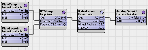
The wire sheet is an example of an actuator configured for a 100 second full-scale drive time. The initial actuator and virtual position values of are set at 0% (synchronized at fully lowered). Should the input signal increase to 40 percent, the raise output turns on for 40 percent of the full scale drive time (40 sec). A subsequent input decrease to 15 percent lowers the output to 25 percent of full scale drive time (25 sec) moving the actuator to 15 percent open.
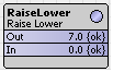
The Voltage Logic: Why 0V, 4V, 7V, 10V?
This confuses everyone at first. The RaiseLower component accepts a 0-10V analog input from your PID loop, but it doesn't just pass that voltage through to the actuator. Instead, it uses voltage thresholds to decide what to do:
The acceptable input to this device is 0 to 10 volts, with staged control at 0v, 4v, 7v and 10v as detailed below:
|
Input Voltage |
Raise Output |
Lower Output |
What Happens |
|
0V |
OFF |
OFF |
Valve does nothing (stays where it is) |
|
4V |
OFF |
ON |
Valve CLOSES (Lower output active) |
|
7V |
OFF |
OFF |
STATIC - valve holds position (neither raise nor lower) |
|
10V |
ON |
OFF |
Valve OPENS (Raise output active) |
The 7V static point is the key to smooth control. When your PID loop is stable, it naturally settles around 7V (70% output), and the RaiseLower component holds the valve in position without unnecessary motor cycling.
Summary: Key Takeaways
-
Know your actuator type
0-10V modulating = 2 wires, position controlled by voltage. Raise/Lower = 3 wires, position controlled by timed pulses.
-
Always use the RaiseLower component for 3-wire actuators
You can't wire a 3-wire actuator directly to analog outputs. The RaiseLower component handles the voltage logic and timing.
-
Get the Drive Time right
This is THE most critical setting. Check the actuator datasheet. If Drive Time is wrong, virtual position will drift.
-
For surveyors: Document everything
Take photos of actuator labels, count wires, record model numbers and drive times. Accurate survey data prevents expensive design errors.
Final Thought
Raise/lower valve control seems complicated at first, but once you understand the fundamentals - physical actuator operation, voltage logic, virtual position tracking - it becomes straightforward. The key is not treating these like 0-10V modulating valves. They're different beasts, and the RaiseLower component is specifically designed to handle their unique requirements.
Other Resources & Customer Survey:
💬 Don't miss out! Follow the Forest Rock News channel on WhatsApp Click Here!
💬 We’d also love your feedback! Please take a moment to complete our quick Customer Survey
It only takes a minute and helps us serve you better!

IoT Devices for BMS, Automation & Smart Connectivity | Forest Rock