

The Phoenix Contact bus coupler can be use with any system using Modbus RTU or Modbus ASCII.
Setup & Configuration Guide
Overview
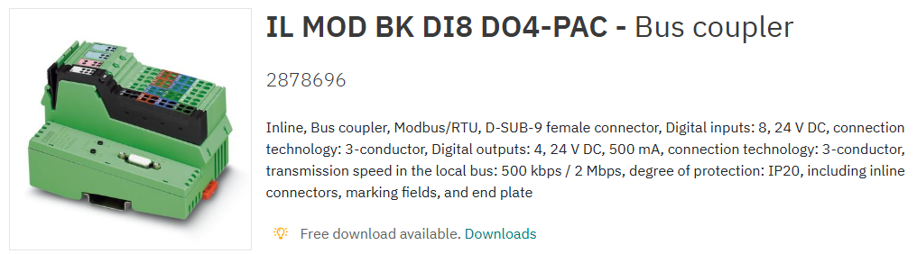
The Phoenix Contact IL MOD BK DI8 DO4‑PAC Modbus RTU/ASCII bus coupler provides a communication bridge between Modbus systems and Phoenix Contact Inline I/O slices. It supports Modbus RTU and Modbus ASCII networks and accepts a wide range of Inline modules, not only those designed for the ILC 2050 platform. [phoenixcontact.com]
The device includes onboard digital inputs and outputs and supports up to 61 Inline devices within a station.
Default Communication Settings
The coupler ships with the following default serial communication parameters:
-
Baud Rate: 19,200
-
Data Bits: 8
-
Stop Bits: 1
-
Parity: EVEN
-
Modbus Address: Configured via two rotary switches (×10 and ×1)
The RS‑485 port supports transmission speeds ranging from 1.2 kbit/s to 115.2 kbit/s, adjustable through configuration.
RS‑485 Physical Connection
Communication is provided via a D‑SUB 9‑pin female connector. The RS‑485 lines are electrically isolated, and shield is tied directly to functional ground.
Pinout (Viewed from Controller Side)
|
Pin |
Signal |
Description |
|---|---|---|
|
3 |
RS‑485 + |
Non‑inverting data line (+) |
|
8 |
RS‑485 – |
Inverting data line (–) |
A custom cable must be soldered to a male D‑SUB 9 plug to match this interface.
Power Supply Considerations
Unless separate PSU isolation is required, all Inline modules can be linked and fed from a single 24 V DC supply.
The bus coupler requires:
-
24 V DC power, with a permissible range of 19.2…30 V DC
-
Sufficient current capacity to support all connected I/O slices
These electrical characteristics match the product’s official specification sheet.
The device includes onboard:
-
8 digital inputs (24 V DC, IEC 61131‑2 Type 1)
-
4 digital outputs (24 V DC, 500 mA each)
Modbus Register Mapping (Static vs Dynamic Tables)
The bus coupler provides two register mapping strategies:
Static Table (Recommended)
-
Provides predictable addressing regardless of slice order
-
Preferred for systems where modules may be added later
Dynamic Table
-
Addressing varies based on physical slot position
-
Not recommended unless specifically required
Digital Input Example – Static Table
-
Slice 1 DI → Register 0000, bits 0–3
-
Slice 2 DI → Register 0001, bits 0–3
-
Slice 3 DI → Register 0002, bits 0–3
(Continues sequentially even if other slice types are present)
Digital Output Example
-
Onboard DOs → Register 0384
-
Additional slices → 0385, 0386, etc.
Plug & Play Mode
What Plug & Play Mode Does
Plug & Play mode allows the bus coupler to auto‑detect Inline slices.
However, when enabled, writing to outputs is blocked—the device must be taken out of this mode for normal operation.
Disabling Plug & Play Mode (Required for Output Control)
-
Set the ×10 rotary switch to 10 (device interprets this as >100).
-
Set the ×1 rotary switch to 4.
-
Power cycle the device.
-
Confirm the watchdog LED flashes every 0.5 seconds.
-
Restore the rotary switches to the original Modbus address.
-
Power cycle again.
The device is now out of Plug & Play mode.
Re‑Enabling Plug & Play Mode (For Adding New Slices)
Repeat the above procedure but set the ×1 rotary switch to 3 instead of 4.
System Capacity & Performance Notes
According to Phoenix Contact:
-
Maximum of 61 Inline devices may be attached (onboard I/Os count as two devices)
-
The Inline local bus operates at 500 kbit/s or 2 Mbit/s, automatically detected
Useful Reference Documentation
Phoenix Contact recommends consulting the Inline System User Manual (IL SYS INST UM E) for installation, wiring, grounding, and full addressing behaviour. This is the master reference for all Inline I/O architectures.
Summary
This Modbus RTU/ASCII bus coupler is highly flexible, supports a broad range of Inline modules, and provides predictable addressing when using the static table. Proper RS‑485 wiring, correct Plug & Play mode handling, and awareness of Inline addressing rules are essential for reliable operation.
Other Resources & Customer Survey:
💬 Don't miss out! Follow the Forest Rock News channel on WhatsApp Click Here!
💬 We’d also love your feedback! Please take a moment to complete our quick Customer Survey
It only takes a minute and helps us serve you better!

IoT Devices for BMS, Automation & Smart Connectivity | Forest Rock