

RUTX10 Powering Options
Power socket
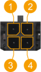
The device has a 4 pin power socket and can be powered by a 9-50 VDC power supply unit (PSU). Refer to the image below for the power socket's pinout information:
|
|
||||||||||||||||||
If you decide not to use the standard wall adapter and want to power the device from a higher voltage (15-50 VDC), please make sure that you choose a power supply of high quality. Some power supplies can produce voltage peaks significantly higher than the declared output voltage, especially during connection and disconnection.
While the device is designed to accept input voltage of up to 50 VDC peaks, high voltage power supplies can harm the device. If you want to use high voltage power supplies it is recommended to also use additional safety equipment to suppress voltage peaks from the power supply.
Suggestion: If you're using a different power supply than the one included in the standard packaging, make sure it meets the same power (W) specifications as the original. Otherwise, some features of the device might not work properly. Please refer to the device's portfolio page to verify the power supply specifications:
|
Test type |
Current (mA) |
Power consumption (W) |
|---|---|---|
|
Idle (9 V) |
377.8 |
3.4 |
|
Idle (12 V) |
280.93 |
3.37 |
|
Idle (24 V) |
146.07 |
3.51 |
Passive PoE
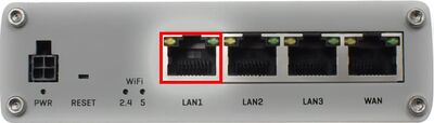
The device may also be powered by an Ethernet cable via the LAN1 port (9-50 VDC):
(Do not use in other ports!)
-
The device is NOT COMPLIANT with the IEEE 802.3af-2003 standard: powering the device from an IEEE 802.3af-2003 power supply will damage the device as it is not rated for input voltages of the PoE standard.
-
The device is NOT COMPLIANT with the IEEE 802.3at standard: it cannot power other devices over Ethernet.
|
|
|
|
|
|
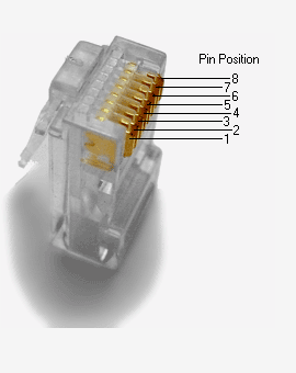
RJ45 pinout: |
|
Pin |
10/100 mode B, DC on spares |
T568A Color |
T568B Color |
Pins on plug face (socket is reversed) |
|
|
1 |
|
TX+ |

white/green stripe |

white/orange stripe |
|
|
2 |
|
TX- |

green solid |

orange solid |
|
|
3 |
|
RX+ |
white/orange stripe |
white/green stripe |
|
|
4 |
DC+ |
9-50 VDC |

blue solid |
blue solid |
|
|
5 |
DC+ |
9-50 VDC |

white/blue stripe |
white/blue stripe |
|
|
6 |
|
RX- |
orange solid |
green solid |
|
|
7 |
DC- |
|

white/brown stripe |
white/brown stripe |
|
|
8 |
DC- |
|

brown solid |
brown solid |
|
Simultaneous powering
The device can be powered from the power socket and over Ethernet simultaneously. The power socket has higher priority meaning that the device will draw power from the power socket as long as it is available.
When the device is switching from one power source to another it loses power for a fraction of a second and may reboot. The device will function correctly after the reboot.
Ground loops
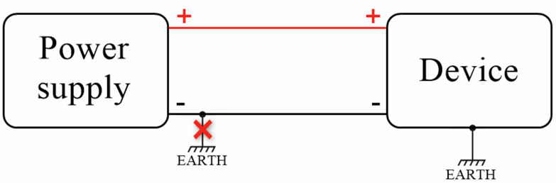
Do not connect the power supply negative terminal of our device to the chassis or earth exclusively.
This connection could cause ground loops. For example, if the antenna shield and power supply negative terminal are connected to the chassis or earth, it forms a ground loop, therefore unwanted current could flow through a device PCB ground and may cause damage.
External Links and Resources:
Passive Power over Ethernet (PoE) - Teltonika Networks Wiki
This article will be updated over time to reflect new suggestions and features with the RUTxxx Hardware