

Table of Contents:
About The Four Digital Input Expander Module:
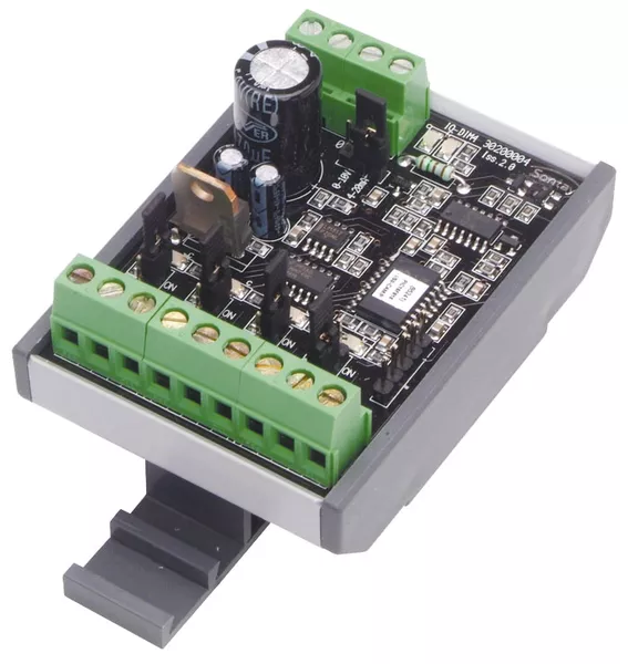
These are developed and sold by Trend, Distech and Sontay as well as a few other manufacturers such as Titan. The Digital Input Expander allows 4 volt free inputs to be monitored by a single analogue input channel on the BMS controller. Traditionally these were developed to reduce the point count on more expensive BMS hardware, but were also handy if a system needed expanding to monitor some status points but your controller only had analogue points spare. The resultant analouge value can be decoded in the controller by an A-D Function Module to produce internal digital status bits for monitoring and alarms, or any other status interlock applications needed to control the HVAC plant.
How would you Decode in Tridium N4:
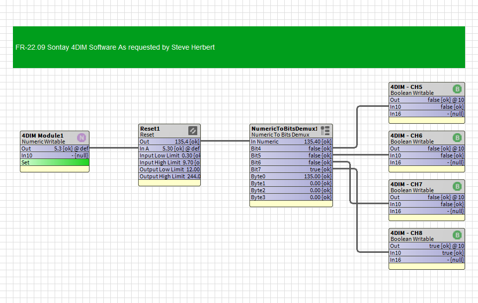
A strategy or Wiresheet software similar to that shown below should be developed and configured in the controller. The software converts the sensor signal received from the expander module and converts that signal in an A-D Module. This Module essentially decodes the single sensor value back to 4 internal corresponding status bits that can be used in software.
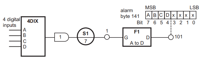
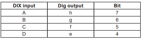
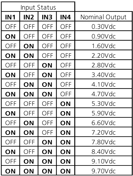
The sensor scaling should be set as shown by the different module manufacturers data sheets, but essentially they are very close and similar. The relationship between the input bits on the module and the software module output bits can be described in the table shown below:
How would you Decode the table above in Tridium N4:
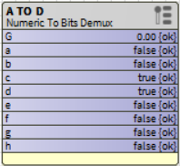
This article makes use of standard kitControl blocks to decode the voltage signal from a Sontay IO-DIM4 digital input multiplexer module into Boolean writable points to represent each of its input statuses. To make the block more familiar to Trend Engineers new to Tridium, we can simply Navigate by right clicking the module and selecting | Views | AX Slot Sheet | where we can change the slot names to the familiar a to h slot names found in a Trend A to D block.
Data Sheets From Sontay
Download full datasheets for these products below.
Conversion In Tridium N4
Make sure the IO-DIM4 output link is set to 0-10V and connected to an input set to read 0-10V with no conversion. All the blocks used here are available within the kitControl palette
Please note - the IO-DIM4 sets its voltage output to set the decoded bits to represent its inputs as follows -
|
Sontay Input |
Module Output Voltage |
Numeric ToBitsDemux - Bit |
|---|---|---|
|
IN 1 |
0.9Vdc |
Bit 7 - ON |
|
IN 2 |
1.6Vdc |
Bit 6 = ON |
|
IN 3 |
2.8Vdc |
Bit 5 - ON |
|
IN 4 |
5.3Vdc |
Bit 4 - ON |
-
Bit 4 = Input 1
-
Bit 5 = Input 2
-
Bit 6 = Input 3
-
Bit 7 = Input 4
Please DO NOT use bits 0 to 3
The Full Sontay Switching Sequence Table
Sensor Scaling
If your using Trend, then a sensor type table is fairly familiar to you, however in Tridium we have to tackle this problem slightly differently. Essentially the sensor input is set up to measure 0-10Vdc but this signal is not the right scaling for an A-D conversion module so we need to create the equivalent of a sensor table in N4.
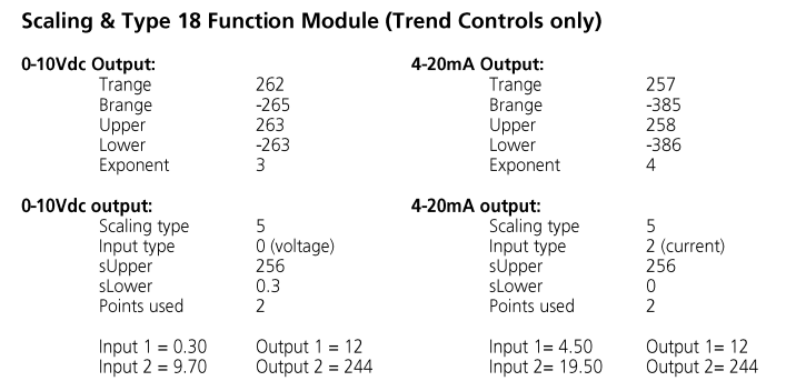
We ignore the top row of scaling values as these are designed purely for Trend Controllers.
We take the second row down and look at the 0-10Vdc output bottom left of the table as shown below.
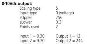
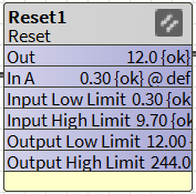
Using a Reset Module from kitControl we add the values from the table above into the Reset Module
|
Sontay Scaling |
Reset Module Settings |
|---|---|
|
Input 1 = 0.3 |
Input Low Limit = 0.3 |
|
Input 2 = 9.7 |
Input High Limit = 9.7 |
|
Output 1 = 12 |
Output Low Limit = 12 |
|
Output 2 = 244 |
Output High Limit = 244 |
The Wiresheet Software
An Alternative Method
The same result can be achieved with a Program component.
Please see this article A to D Converter which will give you a good insight into how to use the Program component.