

Learning Objectives
By the end of this module, learners will be able to:
-
Understand the purpose of IP addresses within building networks.
-
Explain the difference between IPv4 and IPv6.
-
Identify network and host portions of an IP address.
-
Understand subnet masks and CIDR notation.
-
Explain how devices communicate within and across subnets.
-
Understand the role of default gateways.
-
Recognise common addressing schemes used in Building Management Systems.
-
Apply basic subnetting principles to smart building projects.
-
Perform basic IP connectivity troubleshooting.
-
Appreciate the importance of structured IP addressing in scalable smart buildings.
Estimated Reading Time: 12-15 Minutes
Knowledge Level: Beginner to Moderate
Category: Forest Rock Learning Academy
Why IP Addressing Matters
Every device connected to a smart building network requires an identity.
Just as every office has a postal address, every networked device requires an IP address so that information can be delivered to the correct destination.
Without IP addressing:
-
Controllers cannot exchange data.
-
Supervisors cannot discover devices.
-
Engineers cannot remotely access equipment.
-
Cloud platforms cannot collect building information.
As buildings become increasingly connected, understanding addressing and subnetting becomes an essential skill for engineers, consultants, and system integrators.
What Is an IP Address?
An Internet Protocol (IP) address is a logical network address assigned to a device.
It allows devices to:
-
Identify themselves
-
Locate other devices
-
Send information
-
Receive information
Examples of devices requiring IP addresses include:
-
Niagara Supervisors
-
BACnet/IP Controllers
-
Smart Meters
-
Energy Dashboards
-
IoT Gateways
-
Wireless Access Points
-
Engineering Workstations
Think of an IP address as a phone number for a device on a network.
IPv4 Addresses
Most Building Management Systems use IPv4 addresses to identify devices on a network.
An IPv4 address consists of four numbers separated by periods, for example:
192.168.10.50
Each number is called an octet and can have a value between 0 and 255.
Think of an IP address as a building's postal address. It allows data to be sent to the correct device, whether that's a controller, supervisor, energy meter, or workstation.
IPv4 addresses can range from: 0.0.0.0 to 255.255.255.255
However, most smart building systems use addresses from the private IP ranges reserved for local networks.
Real-World Example
A small BMS network might use addresses such as:
-
Niagara Supervisor 192.168.10.10
-
AHU Controller 192.168.10.20
-
Energy Meter 192.168.10.30
-
Engineering Laptop 192.168.10.100
Because all devices share the same network range, they can communicate with each other directly. This forms the foundation of IP-based building automation systems.
Public and Private IP Addresses
In this section, you will learn why building networks usually use private IP addresses, how they differ from public IP addresses, and where port forwarding fits in.
Simple analogy: A private IP address is like a room number inside a building. A public IP address is like the building’s street address. Devices inside the building can find one another using room numbers, while people outside use the street address to reach the building.
Private and public: what is the difference?
|
Address type |
What it is used for |
Example |
|---|---|---|
|
Private IP address |
Identifies a device within a local network, such as a BMS network. It is not directly reachable from the public internet. |
|
|
Public IP address |
Identifies a network or service that can be reached from the internet. |
|
Most controllers, meters, gateways, and supervisory systems in a smart building use private IP addresses. The network router normally uses the site’s public IP address when devices access the internet.
Private IPv4 address ranges
There are three standard ranges reserved for private IPv4 networks:
-
10.0.0.0 – 10.255.255.255 -
172.16.0.0 – 172.31.255.255 -
192.168.0.0 – 192.168.255.255
Addresses in these ranges can be reused in different buildings because they are intended for local networks. For example, a BMS network might use addresses beginning with 192.168.10, while a lighting network uses 192.168.20.
Why private addressing matters
Using private addresses helps engineers to:
-
Reduce direct exposure of building devices to the internet.
-
Organise devices into clear networks, subnets, and VLANs.
-
Reuse standard address ranges across different projects.
-
Plan for future devices and system expansion.
-
Make network management and troubleshooting easier.
Where are private addresses used?
-
BMS networks: controllers and supervisors communicate locally.
-
Energy networks: meters and monitoring systems exchange data.
-
Lighting systems: lighting controllers communicate with management software.
-
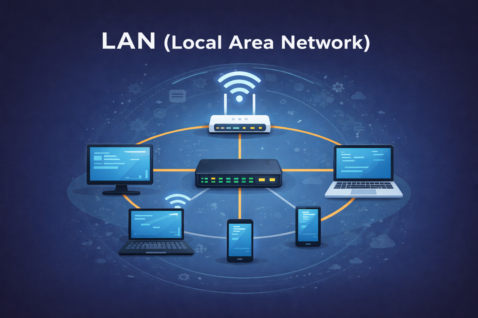
Corporate LANs: computers, printers, and other office devices connect.
Port forwarding
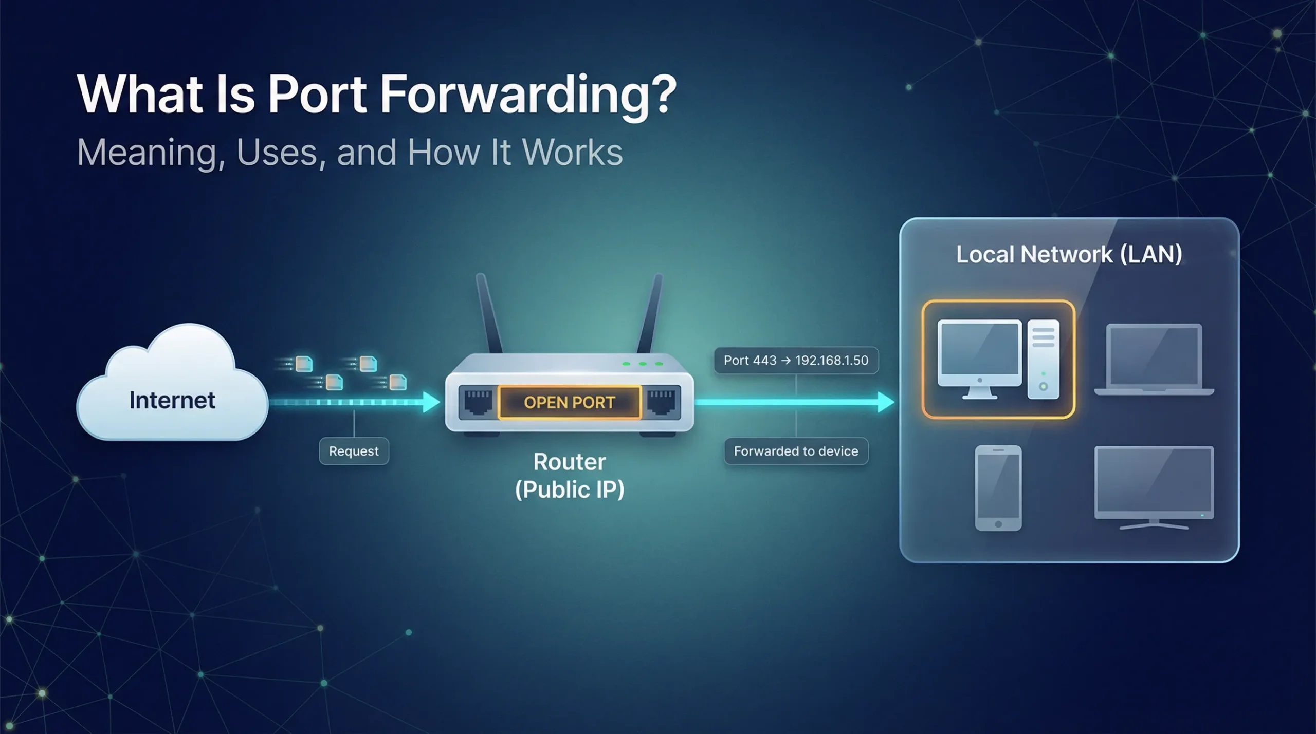
Private devices are normally protected from unsolicited connections from the internet. If an external connection is genuinely required, a router can use a port forwarding rule.
A port forwarding rule sends traffic arriving at a specific public IP address and port to a specific private IP address and port inside the building network.
For example, a rule might direct traffic from the router’s public port 443 to a web service on a BMS server at 192.168.10.20:443.
Security reminder: Use port forwarding only when necessary. Limit the allowed source addresses and ports, apply firewall rules, keep the device updated, and document the rule. A secure VPN is often safer than exposing a BMS device directly to the internet.
Key takeaway
Private IP addresses identify devices inside a local network. A public IP address identifies the site or service from the internet. Routers connect the two, and port forwarding deliberately allows selected incoming traffic to reach a specific private device.
Devices on a local building network do not usually need to be reachable directly from the internet. This is where private IP addresses are useful.
A private IP address identifies a device inside a local network, such as a BMS network. It is not reachable directly from the public internet. A public IP address, by contrast, can identify a network or service that is reachable from the internet.
Three private IPv4 ranges are commonly used:
-
10.0.0.0 – 10.255.255.255 -
172.16.0.0 – 172.31.255.255 -
192.168.0.0 – 192.168.255.255
These devices can communicate freely within the building network, while remaining hidden from direct internet access.
Why This Matters
Private addressing allows engineers to:
-
Reuse standard address ranges across multiple projects.
-
Improve cybersecurity by reducing internet exposure.
-
Create structured addressing schemes that are easier to manage.
-
Support network segmentation using VLANs and subnets.
-
Simplify future expansion and integration.
For most smart building projects, the majority of controllers, meters, gateways, and supervisory systems will operate using private IP addresses.
Private addresses are commonly used for devices such as:
-
BMS networks — controllers and supervisors communicate locally.
-
Energy networks — meters and monitoring systems exchange data.
-
Lighting systems — lighting controllers communicate with management software.
-
Corporate LANs — computers, printers, and other office devices connect.
Key idea: A private IP address is used inside a local network. If a device needs to access the internet, the network router usually sends the traffic out through the site’s public IP address. The private address remains hidden from the internet. A port forwarding rule can deliberately direct incoming traffic received on a specific public port to a specific device and port on the private network. For security, port forwarding should be used only when necessary, restricted to the required source addresses and ports, protected by firewall rules, and documented. A secure VPN is often preferable to exposing a BMS device directly to the internet.
Understanding Network and Host Portions
Every IPv4 address has two logical parts: the network portion and the host portion. Together, they tell a device which network it belongs to and which individual device should receive the data.
Learning objective: By the end of this section, you should be able to identify the network and host portions of a basic IPv4 address.
1. The network portion
The network portion identifies the network or subnet. Devices with the same network portion are on the same logical network and can usually communicate directly.
2. The host portion
The host portion identifies a specific device on that network. Each device on the same subnet must have a different host portion.
Worked example
Consider the address 192.168.10.50/24.
With a /24 prefix, the first 24 bits identify the network and the remaining 8 bits identify the host. In the familiar dotted-decimal format, this is:
IP address:       192.168.10.50
Network portion:  192.168.10
Host portion:                  50
In this example:
-
192.168.10 identifies the network.
-
50 identifies the individual device, such as a controller or supervisor.
Why the split matters
When a device needs to send data, it compares the destination address with its own network portion. If the network portions match, it sends the data directly across the local network. If they do not match, it sends the data to a router, usually through the default gateway.
Important: The exact boundary between the network and host portions is defined by the subnet mask or CIDR prefix. Do not assume that the first three numbers are always the network portion.
Key takeaway
The network portion identifies where a device is. The host portion identifies which device it is. The subnet mask tells devices where one portion ends and the other begins.
What Is a Subnet Mask?
A subnet mask works with an IPv4 address to show which part identifies the network and which part identifies the individual device, called the host.
Learning objective: By the end of this section, you should be able to read a basic subnet mask and explain what /24 means.
Why subnet masks are needed
An IP address has two parts:
-
Network portion: identifies the network or subnet.
-
Host portion: identifies a particular device on that network.
The subnet mask marks the boundary between these two portions. Devices use this boundary to decide whether to send traffic directly to another device or through a router.
Worked example: 255.255.255.0
Consider a device configured with the following address and subnet mask:
IP address:    192.168.10.50
Subnet mask:   255.255.255.0
In this example, the first three octets identify the network and the final octet identifies the host:
Network:       192.168.10.0
Host:          50
This means the device belongs to the 192.168.10.0 network. Other devices in the same subnet might include 192.168.10.20 and 192.168.10.100.
CIDR notation: /24
The subnet mask 255.255.255.0 is commonly written in CIDR notation as /24. The number after the slash tells us how many of the address's 32 bits belong to the network portion.
-
/24means 24 bits identify the network. -
The remaining 8 bits identify hosts.
-
A typical
/24subnet provides up to 254 usable host addresses.
How devices use the mask
Suppose a controller at 192.168.10.50/24 needs to communicate with a supervisor at 192.168.10.100/24. Their network portions match, so they can communicate directly on the local network.
If the supervisor were on a different network, such as 192.168.20.100, the controller would send the traffic to its default gateway. The gateway is usually a router that connects different networks.
Important: Do not assume that the first three numbers are always the network portion. The subnet mask or CIDR prefix defines the boundary. For example, a /16 mask creates a different network boundary from a /24 mask.
Quick practice
For the address 10.20.5.25/24, identify the network and host portions.
-
Network:
10.20.5.0 -
Host:
25
Key takeaway
A subnet mask tells devices where the network portion ends and the host portion begins. In a /24 network such as 192.168.10.0/24, the first three octets identify the network and the last octet identifies the device.
Why Subnetting Is Important
Subnetting means dividing one large network into smaller, more manageable networks called subnets.
Learning objective: By the end of this section, you should be able to explain why networks are divided into subnets and describe the main benefits for a smart building.
Why do we use subnetting?
Imagine a large building with one reception area for every person, department, delivery, and visitor. Finding the right person would become slow and difficult. Subnetting works in a similar way: it divides a busy network into logical sections so that devices and traffic are easier to organise.
Each subnet can contain a specific group of devices, such as BMS controllers, lighting equipment, energy meters, or corporate computers. Devices in the same subnet can communicate locally, while traffic between different subnets is controlled by network equipment such as a router or Layer 3 switch.
Four key benefits
1. Scalability
Subnetting creates organised sections for different systems and makes it easier to add new devices as a building grows. For example, a project can reserve one subnet for BMS devices and another for future expansion.
2. Performance
Devices do not all need to process every piece of network traffic. Keeping related devices together reduces unnecessary traffic and helps the network operate more efficiently.
3. Security
Subnets can separate systems from one another. Access between them can then be restricted using firewalls and network rules. For example, CCTV devices can be separated from BMS controllers and corporate computers.
4. Troubleshooting
When a fault occurs, smaller network sections make it easier to identify where the problem is. Engineers can check the affected subnet, its devices, and its network settings without investigating the entire building network at once.
Smart building example
A building might use separate subnets for:
-
BMS: controllers and supervisory systems
-
Lighting: lighting controllers and gateways
-
Metering: energy meters and monitoring devices
-
Corporate IT: staff computers and business systems
These systems may still need to exchange approved data, but the network can control which traffic is allowed between them.
Important: Subnetting improves organisation and can support security, but it does not automatically secure a network. Firewalls, VLAN configuration, access controls, and good network administration are also required.
Quick check
Why might a hospital place BMS, CCTV, and corporate IT devices on different subnets?
Answer: To organise the systems, reduce unnecessary traffic, limit unauthorised access, and make faults easier to isolate.
Key takeaway
Subnetting divides a large network into smaller logical networks. This makes smart building networks easier to scale, more efficient, easier to protect, and simpler to troubleshoot.
Without subnetting, large networks become difficult to manage.
Subnetting improves:
Scalability
Separates systems into manageable sections.
Performance
Reduces unnecessary network traffic.
Security
Allows segmentation between systems.
Troubleshooting
Faults are easier to identify and isolate.
Smart Building Example
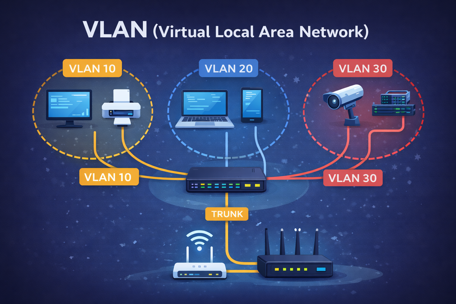
A hospital may separate systems into dedicated VLANs and subnets:
|
System |
Subnet |
|---|---|
|
BMS |
10.10.10.0/24 |
|
Lighting |
10.10.20.0/24 |
|
Metering |
10.10.30.0/24 |
|
CCTV |
10.10.40.0/24 |
|
Corporate IT |
10.10.50.0/24 |
This improves resilience and security while simplifying administration.
Default Gateways
A default gateway is the device that a computer, controller, or other network device uses to reach a different network. In most building networks, the default gateway is the local router.
Learning objective: By the end of this section, you should be able to explain what a default gateway does and identify it in a device's network settings.
Start with the subnet
Devices first check whether the destination is on the same subnet as themselves. The subnet mask helps them make this decision.
-
Same subnet: the device can usually send the data directly to the destination.
-
Different subnet: the device sends the data to the default gateway, which forwards it towards the destination.
Simple analogy: Imagine your subnet as one department in a building. You can deliver a message directly to someone in the same department. If the message is for another department, you give it to reception. The default gateway acts like that reception desk.
Worked example
Consider this controller configuration:
IP address:      192.168.10.50
Subnet mask:     255.255.255.0
Default gateway: 192.168.10.1
The subnet mask shows that the controller is on the 192.168.10.0/24 network.
What happens when it sends data?
-
If the destination is
192.168.10.100, it is on the same subnet. The controller sends the data directly. -
If the destination is
10.10.20.15or a service on the internet, it is on a different network. The controller sends the data to192.168.10.1. -
The router receives the data and forwards it to the correct network.
Important points
-
The default gateway must be reachable from the device's own subnet.
-
Devices on the same subnet may communicate without using the gateway.
-
A device usually needs a correctly configured gateway to communicate beyond its local subnet.
-
The gateway address is not the same as the device's IP address; it belongs to the router or Layer 3 interface.
Troubleshooting tip: If a device can communicate with nearby devices but cannot reach another subnet or the internet, check its default gateway, subnet mask, VLAN, and physical network connection.
Quick check
A controller at 192.168.10.50/24 needs to communicate with a supervisor at 192.168.20.100/24. Which device should receive the traffic first?
Answer: The traffic should be sent to the controller's default gateway, such as 192.168.10.1. The router then forwards it towards the 192.168.20.0/24 network.
Key takeaway
The default gateway is the route out of a device's local subnet. Use direct communication for devices on the same subnet; use the default gateway when the destination is on another network.
A device can communicate directly only with devices on its own subnet.
To communicate with a device on another subnet, traffic must pass through a router.
Device Discovery in Building Systems
Device discovery is the process of finding devices on a network and learning how to communicate with them. In a smart building, discovery allows a supervisor, controller, or software platform to locate equipment such as sensors, meters, gateways, and other controllers.
Learning objective: By the end of this section, you should be able to explain how IP addressing supports device discovery and describe how common building protocols use network addresses.
What does “discovery” mean?
Before two systems can exchange useful data, they need to know where to find each other. Discovery usually involves identifying a device’s network address and then learning additional information, such as its name, device type, available services, or communication points.
Think of a building reception desk. A visitor first needs the building address, then the correct department, room, and person. Network discovery works in a similar way:
-
Find the network location: use an IP address or a DNS name.
-
Identify the device: confirm what the device is and what system it belongs to.
-
Connect using the protocol: use the correct service, port, and communication settings.
-
Exchange information: read values, send commands, or share status information.
Why IP addressing matters
An IP address provides the basic network location of a device. For example, a supervisor may connect to a controller at 192.168.10.20. The supervisor uses the subnet mask to determine whether the controller is on the local network. If it is on another subnet, the traffic is sent through the default gateway.
IP addressing does not, by itself, explain what a device does. It only provides the route to reach it. The building protocol then provides the rules for identifying devices and exchanging data.
Remember: An IP address is like a street address. A protocol is like the language and rules used when communicating with the person at that address.
How discovery works in practice
A typical discovery process might look like this:
-
Connect the engineering workstation or supervisor to the correct network or VLAN.
-
Confirm the device has a valid IP address, subnet mask, and—where required—default gateway.
-
Check that the device is powered, connected, and using the expected protocol settings.
-
Use the protocol’s discovery method to find the device or enter its IP address manually.
-
Verify the returned device details and select the points, services, or data needed by the system.
-
Save the configuration and test communication by reading a value or checking device status.
Discovery may be automatic, semi-automatic, or manual. Automatic discovery is convenient, but it can be limited by routers, firewalls, VLAN boundaries, or protocol-specific settings. Manual configuration is often used when a device is on another subnet or when a controlled and documented configuration is preferred.
Common protocols used in building systems
BACnet/IP
BACnet/IP uses IP networking to transport BACnet messages. Devices also have BACnet-specific information, such as a device instance and object identifiers. An engineer may discover a controller, confirm its BACnet device instance, and then browse its points.
Discovery is usually easiest when devices are on the same subnet. When BACnet/IP devices are separated by routers, additional configuration may be needed so that discovery messages can cross the network boundary.
MQTT
MQTT normally uses a broker rather than having every device communicate directly with every other device. A client connects to the broker using an IP address or DNS name, then publishes or subscribes to named topics.
For example, a temperature gateway might publish data to a topic such as building/floor1/room101/temperature. The IP address helps the gateway find the broker; the topic tells the broker where the message belongs.
REST APIs
REST APIs allow software systems to exchange information using web requests. A client connects to a server by using its IP address or hostname, a port, and a URL path.
For example, a dashboard might request an energy value from https://bms.example.local/api/energy. DNS translates the hostname into an IP address, and the API defines the data request and response.
Niagara
Niagara uses IP networking for platform management, station communication, histories, alarms, and integrations. A Niagara Supervisor may connect to remote stations using their IP addresses or hostnames, then discover and configure the available services and points.
If a Niagara station cannot be discovered, the cause may be an incorrect IP address, subnet, gateway, firewall rule, service configuration, or an unavailable station—not necessarily a fault in the station’s application logic.
Same subnet and different subnet
Discovery is often simplest when the workstation and device are on the same subnet. For example, 192.168.10.100/24 and 192.168.10.20/24 share the network 192.168.10.0/24, so they can usually communicate directly.
If the device is at 192.168.20.20/24, it is on a different subnet. Traffic must pass through a router, and the relevant protocol must be allowed across the network boundary. A successful ping does not always mean that protocol discovery will work, because firewalls and protocol services may use different ports or message types.
Beginner troubleshooting checklist
If a device does not appear during discovery, work through these checks in order:
-
Power and cabling: Is the device powered and connected to the correct switch port?
-
IP settings: Is the address correct, unique, and in the expected subnet?
-
Subnet and gateway: Are the subnet mask and default gateway correct for the device location?
-
VLAN: Is the workstation or device connected to the intended VLAN?
-
Basic connectivity: Can the device be reached with a ping, where permitted?
-
Protocol service: Is the required service enabled and listening on the expected port?
-
Firewall rules: Is traffic allowed between the source and destination networks?
-
Names and credentials: If using DNS or an API, are the hostname, URL, username, and password correct?
Important: Do not change IP addresses or firewall rules without recording the original settings and following the project’s change-control process. Incorrect changes can interrupt live building services.
Worked example
An engineer wants to add an AHU controller to a Niagara Supervisor.
-
The controller is assigned
192.168.10.20with a255.255.255.0subnet mask. -
The Supervisor is at
192.168.10.100on the same subnet. -
The engineer confirms that the controller has a unique address and responds to a connectivity test.
-
The Niagara station discovers the controller and displays its available points.
-
The engineer checks a live temperature value and records the device details in the addressing schedule.
If the controller were moved to 192.168.20.20, the Supervisor would need a route through the default gateway, and the network would need to permit the required Niagara or protocol traffic.
Quick check
Why might a device respond to a ping but still fail to appear during BACnet/IP, MQTT, REST, or Niagara discovery?
Answer: Ping only tests basic IP reachability. The required protocol service may be disabled, blocked by a firewall, configured on the wrong port, restricted to another VLAN, or unable to cross a router boundary.
Key takeaway
Device discovery combines IP networking with protocol-specific rules. The IP address helps a system find the device, while the protocol explains how to identify the device and exchange data. Always check the address, subnet, gateway, VLAN, service, and firewall path when discovery fails.
IPv6: The Next Generation of IP Addressing
Most building systems still use IPv4, but you may increasingly encounter IPv6. IPv6 was created because the world is running out of IPv4 addresses and because modern networks need to connect many more devices.
Learning objective: By the end of this section, you should be able to explain the main differences between IPv4 and IPv6 and describe why IPv6 may become more important in smart buildings.
Why was IPv6 created?
IPv4 provides about 4.3 billion addresses. That sounds like a large number, but phones, computers, cameras, controllers, meters, vehicles, and other connected devices use addresses. Many IPv4 addresses are also reserved for specific purposes, so the number available for public use is smaller.
IPv6 uses 128-bit addresses instead of IPv4's 32-bit addresses. This creates an extremely large address space—enough for the continuing growth of the internet and the Internet of Things (IoT).
What does an IPv6 address look like?
An IPv6 address is written as eight groups of hexadecimal characters separated by colons:
2001:0db8:85a3:0000:0000:8a2e:0370:7334
Hexadecimal uses the numbers 0–9 and the letters A–F. IPv6 addresses can be shortened by removing leading zeroes and replacing one consecutive run of zero groups with ::. For example:
2001:0db8:0000:0000:0000:0000:0000:0042
2001:db8::42
The two lines represent the same IPv6 address. The shortening rules make addresses easier to write, but they can look unfamiliar at first.
IPv4 and IPv6: the main differences
|
Feature |
IPv4 |
IPv6 |
|---|---|---|
|
Address length |
32 bits |
128 bits |
|
Written as |
Four decimal numbers separated by full stops, for example |
Eight hexadecimal groups separated by colons |
|
Address capacity |
Limited |
Extremely large |
|
Private or local addressing |
Commonly uses ranges such as |
Uses local and unique address ranges, depending on the network design |
|
Configuration |
Often configured manually or with DHCP |
Can use automatic configuration as well as DHCPv6 or manual settings |
How IPv6 differs in everyday use
The basic idea is the same: an IP address identifies a network interface and helps deliver traffic to the correct destination. However, IPv6 uses different notation and configuration methods.
-
No broadcast traffic: IPv6 uses multicast and other mechanisms instead of IPv4 broadcast messages.
-
Automatic addressing: devices can often create their own address using information advertised by a router. This is called SLAAC (Stateless Address Autoconfiguration).
-
Subnets are written differently: IPv6 commonly uses a prefix such as
/64to identify the network portion. -
NAT is not normally required: IPv6 has enough addresses for devices to have globally unique addresses. Firewalls are still essential; a globally unique address does not mean a device should be openly reachable.
Why might IPv6 matter for smart buildings?
Smart buildings are adding more connected devices, including sensors, room controllers, lighting systems, meters, access-control equipment, and cloud-connected gateways. IPv4 can support many deployments today, but future projects may need more addresses than an IPv4 plan can conveniently provide.
IPv6 may help organisations to:
-
Provide a unique address for a very large number of devices.
-
Support new IoT devices without relying as heavily on address-sharing techniques.
-
Connect buildings, campuses, and cloud services as networks continue to grow.
-
Use modern operating systems, wireless networks, and managed services that increasingly support IPv6.
-
Prepare for customer, regulatory, or supplier requirements that expect IPv6 capability.
Important for newcomers: IPv6 is not simply a larger version of IPv4. It has different address notation, discovery behaviour, configuration methods, and troubleshooting tools. A device or application must support IPv6; an IPv4 address cannot be converted into an IPv6 address by changing its format.
What does this mean for BMS projects today?
Many BMS controllers and integration projects still operate mainly on IPv4. This does not mean IPv6 can be ignored. Engineers may need to confirm whether controllers, supervisors, switches, firewalls, VPNs, monitoring tools, and building protocols support IPv6.
During design and commissioning, ask:
-
Does the device support IPv6, or is it IPv4-only?
-
Will IPv4 and IPv6 operate together on the network?
-
Are the required firewall, VLAN, DNS, and monitoring rules in place?
-
Does the supplier document IPv6 addressing and discovery requirements?
-
Is the addressing plan recorded for future maintenance?
Many networks use dual stack, which means IPv4 and IPv6 operate alongside each other. This allows organisations to introduce IPv6 gradually while existing IPv4 equipment continues to work.
Quick check
Why might a future smart building need IPv6 even if its current BMS uses IPv4?
Answer: The building may connect many more sensors, controllers, and services than an IPv4 plan can comfortably support. IPv6 provides a much larger address space and helps prepare the network for future technologies and requirements.
Key takeaway
IPv4 remains common in building management systems, but IPv6 provides a vastly larger address space and supports the continued growth of connected devices. For newcomers, the most important points are that IPv6 addresses look different, use different configuration and discovery methods, and may be introduced alongside IPv4. Understanding IPv6 now will make future smart-building projects easier to design, commission, and troubleshoot.
IPv4 addresses are limited in quantity.
IPv6 was developed to provide a significantly larger address space.
Although most BMS deployments continue to use IPv4, awareness of IPv6 is increasingly important.
Common IP Addressing Mistakes
Small addressing errors can prevent controllers, supervisors, meters, and other building systems from communicating. Learning to recognise these mistakes will make commissioning and troubleshooting much easier.
Learning objective: By the end of this section, you should be able to identify common IP addressing mistakes, recognise their symptoms, and carry out basic checks before escalating a fault.
1. Duplicate IP addresses
Two devices must not use the same IP address on the same network. If they do, network traffic may be sent to the wrong device, or communication may work intermittently.
Typical symptoms: devices appear and disappear, connections drop, or the wrong device responds.
Check: compare the device address with the addressing schedule and confirm that every address is unique.
2. Incorrect subnet mask
The subnet mask tells a device which addresses are local and which are on another network. If it is wrong, devices may try to communicate directly when they should use a router, or may send local traffic to the gateway.
Typical symptoms: some devices can be reached, but others on the same or a different subnet cannot.
Check: verify the subnet mask against the approved network design. A common example is 255.255.255.0, also written as /24.
3. Missing or incorrect default gateway
The default gateway is normally the router that connects the local subnet to other networks. It is not usually needed for communication within the same subnet, but it is required to reach another subnet or an external service.
Typical symptoms: local communication works, but the device cannot reach a supervisor on another VLAN, a time server, or the internet.
Check: confirm that the gateway address belongs to the correct router interface and is reachable from the device’s subnet.
4. Incorrect DNS settings
DNS translates a name, such as supervisor.example.local, into an IP address. If DNS is incorrect, a device may be reachable by IP address but not by name.
Typical symptoms: a hostname or web address fails, while connecting directly to the IP address works.
Check: verify the DNS server address, hostname spelling, and local DNS records. Do not confuse DNS with the default gateway: DNS finds names, while the gateway forwards traffic between networks.
5. Device on the wrong VLAN
A VLAN is a logical network segment. A device connected to the wrong VLAN may receive an address from the wrong network or be unable to communicate with the systems it needs.
Typical symptoms: the device has an unexpected IP address, cannot be discovered, or cannot reach devices that should be available.
Check: confirm the switch port, wireless network, VLAN assignment, and expected IP range with the network administrator.
6. Documentation errors
An addressing schedule should record each device’s name, location, IP address, subnet mask, gateway, VLAN, and relevant protocol details. Incorrect or outdated records can cause engineers to configure the wrong device or reuse an address.
Typical symptoms: the configured address does not match the drawings or schedule, or nobody can confirm which device owns an address.
Check: update the documentation after every approved change and label equipment clearly.
A simple checking sequence
-
Confirm that the device is powered and connected to the correct network port.
-
Check the IP address is correct, unique, and in the expected range.
-
Check the subnet mask and default gateway.
-
Confirm the VLAN and physical connection.
-
Test basic connectivity where permitted, then check the required protocol and service.
-
Record the results and any approved changes.
Safety and change control: Do not change live network settings without approval. Record the original configuration first, follow the project change process, and consider the effect on operating building services.
Quick check
A controller can communicate with devices on its own subnet but cannot reach a supervisor on another VLAN. Which settings should you check first?
Answer: Check the subnet mask, default gateway, VLAN assignment, routing, and firewall rules. Also confirm that the supervisor’s address and required protocol service are correct.
Key takeaway
Most addressing faults can be narrowed down by checking the device’s address, subnet mask, gateway, DNS, VLAN, and documentation in a consistent order. A clear, maintained addressing plan prevents many problems before commissioning begins.
Many commissioning issues originate from simple addressing errors.
Common examples:
-
Duplicate IP addresses
-
Incorrect subnet masks
-
Missing default gateways
-
Incorrect DNS settings
-
Devices configured on the wrong VLAN
-
Documentation errors
A structured addressing plan prevents many of these problems.
Basic IP Troubleshooting: A Simple Step-by-Step Guide
When a controller, supervisor, or other building device cannot communicate, work through these checks in order. Start with the simplest checks and move towards the network and protocol settings.
Goal: Find out whether the problem is with the connection, the device settings, the network path, or the communication protocol.
Before you begin
-
Record the device name, location, and expected IP address.
-
Have the approved IP addressing schedule available.
-
Follow your site’s change-control process. Do not change live settings without permission.
Step 1: Check power and cables
Make sure the device is powered on. Check that the network cable is firmly connected at both ends and that the switch port shows a link light.
If this fails: restore power or correct the cable or switch-port connection before continuing.
Step 2: Check the IP address
Confirm that the device has the expected IP address and that the address is unique on the network.
Look for: a missing address, an address in the wrong range, or another device using the same address.
Step 3: Check the subnet mask
Confirm that the subnet mask matches the network design. A common example is 255.255.255.0, also written as /24.
The mask tells the device which destinations are local and which require a router.
Step 4: Check the default gateway
If the device needs to communicate with another subnet, confirm that its default gateway is correct and belongs to the router for its network.
Typical clue: local devices respond, but devices on another VLAN or network do not.
Step 5: Test basic connectivity
From an approved workstation, ping the device where site policy allows it.
-
Ping succeeds: basic IP connectivity is working. Continue to check the protocol.
-
Ping fails: recheck the IP address, subnet mask, gateway, VLAN, cable, and firewall path.
Step 6: Check the VLAN and network path
Confirm that the device and the workstation are connected to the intended VLAN. If they are on different subnets, check that routing is available between them.
Ask the network administrator to confirm the switch port, VLAN assignment, routing, and firewall rules.
Step 7: Check the protocol
Once basic IP connectivity works, confirm that the required service is enabled and correctly configured. Check the protocol, port, device settings, credentials, and any firewall rules.
A successful ping does not guarantee that BACnet/IP, MQTT, REST, Niagara, or another service will work.
Use this decision path
-
No power or link light? Fix the physical connection.
-
Incorrect or duplicate IP address? Correct it using the approved addressing schedule.
-
Same-subnet communication works but another network fails? Check the subnet mask, gateway, VLAN, routing, and firewall.
-
Ping works but the system cannot discover the device? Check the protocol service, port, credentials, and application configuration.
Safety and change control: Record the original settings before making any change. Obtain approval, make one change at a time, and test the building service afterwards.
Key takeaway
Check in this order: power and cables → IP address → subnet mask → gateway → ping → VLAN and routing → protocol. This consistent sequence helps you locate the fault without changing settings unnecessarily.
Network Design Support for Partners
Forest Rock provides network design and advisory support as a paid professional services offering for partners delivering smart-building and building-management projects.
Whether you are planning a new installation, upgrading an existing site, or integrating multiple building systems, our engineers can provide specialist network-design guidance from early planning through commissioning. The scope of work is agreed with you in advance and is tailored to the requirements, complexity, and stage of your project.
Our objective: help you create a network that supports reliable system communication, straightforward commissioning, future expansion, and secure day-to-day operation.
Professional services and quotation: This is not a free service. Network design, review, documentation, commissioning, and troubleshooting support are delivered as professional services by Forest Rock. We will review your requirements and provide a quotation for the work needed before any services begin. The quotation will set out the agreed scope, deliverables, assumptions, timescales, and fees.
How we can help
Network architecture and addressing plans
We work with you to define a clear network structure before deployment begins. This can include IP addressing schemes, subnet design, VLAN requirements, gateway planning, and allocation of addresses for controllers, supervisors, gateways, meters, and other connected devices.
Segmentation and security
We help identify sensible boundaries between building systems and corporate or guest networks. Our recommendations can support the use of VLANs, subnets, routing, firewall rules, and controlled access between systems, while limiting unnecessary exposure.
Scalability and future readiness
We design with future requirements in mind, allowing space for additional devices, new systems, phased construction, and evolving smart-building services. This reduces the risk of having to redesign the network as the project grows.
Integration and connectivity planning
We consider how BMS platforms, lighting, metering, IoT gateways, cloud services, remote access, and other systems need to communicate. Where relevant, we help define the network paths and protocol requirements needed for successful integration.
Commissioning and troubleshooting support
We can support partners with addressing schedules, device connectivity checks, discovery issues, and structured fault-finding. A documented design makes it easier to identify problems and resolve them efficiently during commissioning and throughout the system lifecycle.
Our approach
-
Review the project requirements, systems, site constraints, and stakeholder responsibilities.
-
Develop a structured addressing and segmentation proposal.
-
Identify required network services, routing, firewall rules, and access arrangements.
-
Document the design in a format that can be used by installers, network teams, and commissioning engineers.
-
Support implementation, testing, and resolution of network-related issues where required.
Typical deliverables
-
IP addressing and subnet schedules
-
VLAN and network-segmentation recommendations
-
Network architecture and connectivity diagrams
-
Gateway, routing, firewall, and remote-access requirements
-
Device and system communication requirements
-
Commissioning checklists and troubleshooting guidance
-
Recommendations for documentation and ongoing support
Important: Network changes should be agreed with the site owner and managed by the responsible IT or network team. Our recommendations complement, but do not replace, the client’s security policies, approvals, and operational change-control processes.
Benefits for your projects
-
Clearer responsibilities between building-services, IT, and network teams
-
Fewer addressing and connectivity issues during commissioning
-
Improved security through planned segmentation and controlled access
-
A network that can accommodate future devices and integrations
-
Better documentation for handover, maintenance, and lifecycle support
Discuss your requirements
If you need assistance designing or reviewing a network for a smart-building project, speak to the Forest Rock team. We will discuss your requirements, clarify the scope of support, and provide a quotation for the professional services necessary—from an initial design review to detailed addressing plans, network documentation, and commissioning assistance. Work will begin only after the scope and quotation have been agreed.
Contact Forest Rock to discuss your requirements and request a quotation for the professional services needed to support your project.
Summary and next steps
This module has introduced the essential IP-addressing concepts used in smart-building networks. You should now understand that an IP address identifies a device, while the subnet mask defines the network it belongs to and the host that identifies the individual device. You should also understand that devices on the same subnet can usually communicate directly, while traffic to another subnet is sent through the default gateway.
These skills help building-automation professionals plan private and public addressing, divide networks into appropriate subnets, support device discovery, and troubleshoot connectivity in a structured way. IPv4 remains common in BMS projects, but understanding the key differences between IPv4 and IPv6 will help you prepare for future smart-building networks and larger numbers of connected devices.
Key takeaway: Good IP addressing is not just about assigning numbers. It provides a clear structure for communication, security, commissioning, maintenance, and future expansion.
Knowledge Check
-
What is an IP address, and what does it allow a device to do on a network?
-
In the address
192.168.10.50/24, what is the network address and what is the host identifier? -
What does a subnet mask or CIDR prefix such as
/24tell a device? -
Two devices are on the same subnet. How will they normally communicate with each other?
-
What is the role of a default gateway, and when is it needed?
-
Which of these is a private IPv4 address:
192.168.10.20,8.8.8.8, or203.0.113.10? Explain your choice. -
Why might a building network use separate subnets or VLANs for BMS, lighting, CCTV, and corporate IT?
-
What is port forwarding, and why should it be used cautiously on a BMS network?
-
Why might a device respond to a ping but still fail to appear during BACnet/IP, MQTT, REST, or Niagara discovery?
-
A controller can communicate with devices on its own subnet but cannot reach a supervisor on another VLAN. Which settings should you check first?
-
What is one important difference between IPv4 and IPv6, and why might IPv6 become more important in future smart buildings?
-
List the recommended basic troubleshooting order from the physical connection through to the communication protocol.
If you need more help:
Then why not contact our sales or support team.
sales@forestrock.co.uk or support@forestrock.co.uk
Learn | Integrate | Innovate
Welcome to the Forest Rock Learning Academy.
Real Knowledge. Real Engineers. Real Solutions.